So I powered up PSU boards for xbosoz kit and measured +9 and 0 right before I started to see smoke!
I tried the second board same thing, not sure what to start checking to confirm PSU boards.
Before hooking up the boards I checked power supply was +70 and -28. Any suggestions would be great.
Thanks,
Pathmark
I tried the second board same thing, not sure what to start checking to confirm PSU boards.
Before hooking up the boards I checked power supply was +70 and -28. Any suggestions would be great.
Thanks,
Pathmark
The PSU was working properly by itself and then smoked when you connected the XBOSOZ, correct? I'll venture a guess that you got at least some of the 1000 uf caps in backwards on the XBOSOZ. You'll probably need to replace the caps.
That or you fried your fets (check for very high to infinite resistance Source to Drain in either direction. If not, they need replacing). Handle them carefully - a little static on the gate is all you need to fry them.
That or you fried your fets (check for very high to infinite resistance Source to Drain in either direction. If not, they need replacing). Handle them carefully - a little static on the gate is all you need to fry them.
More details
Sorry if not enough details. The boards are twisted pear audio based on Terry (metalman) schematic.
The xbosoz boards were not attached I was simply checking the PSU rails. Again on power-up the measured +9 and 0 (+ and - rails respectively) and then some smoke.
Pathmark
Sorry if not enough details. The boards are twisted pear audio based on Terry (metalman) schematic.
The xbosoz boards were not attached I was simply checking the PSU rails. Again on power-up the measured +9 and 0 (+ and - rails respectively) and then some smoke.
Pathmark
")
Pathmark-
Are you using two transformers?
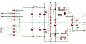
I did not look up the Twisted pear wiring diagram, but the ps diagram you posted looks the same (as far as trafo wiring goes) as Nelson's original article.
When I first hooked up my BOSOZ ps, I tried to use a single transformer. I believe I had it wired wrong, which caused the magic smoke to quickly exit the bridges.
JJ
Are you using two transformers?
I did not look up the Twisted pear wiring diagram, but the ps diagram you posted looks the same (as far as trafo wiring goes) as Nelson's original article.
When I first hooked up my BOSOZ ps, I tried to use a single transformer. I believe I had it wired wrong, which caused the magic smoke to quickly exit the bridges.
JJ

Pathmark-
I would check those wimpy little 4004's to see if they are blown.
Also, if you have an unregulated power supply laying around, you can use it to check the regulated portion of the circuit past the diodes. A lower voltage PS, say +- 20 volts is better for this. (after doublechecking to see everything is installed correctly, of course.)
Just connect ground to ground, V+ to the junction between R1 and C1, and V- to the junction between R2 and C2. Your regulated voltage out will app. 3 to 4 volts less than your unregulated voltage.
JJ
- Status
- This old topic is closed. If you want to reopen this topic, contact a moderator using the "Report Post" button.
- Home
- Amplifiers
- Pass Labs
- A little XBOSOZ help