Hello together
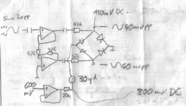
I have build this little diodering vca core. Want to design a compressor with it.
The couloring of the sound is very pleasant, problem is that when the output exceeds 40mVpp you get very nasty clipping.
In the shematics i have included meassurements of AC and DC for different points, as well as the current through the diode ring.
Diodes are BAT43.
A 2Vpp sine was applied to the input, the cv was adjusted to max output without clipping.
With higher cv the level is reduced.
Ok, now i need to amplify the signal, bring it back to about 2Vpp
Jusit not sure witch way to go.
The signal is balanced, so i could immagine using some kind of instrumention amp like the INA103. That has best performance with source impedances of 200r
I have no idea what the impedance of my vca is. Guess it will vary with the current flowing through the ring.
What method of amplification would you recomend for best performance?
PS. when it´s done i can post the complete schematic and layout.
cheers
Attachments
Hi 
I have also try the audio compressor circuit for the speaker telephone.
(the local signal is very high and remote it is too low)
I can use a NE570 compandor (ON semi)
http://www.onsemi.com/pub/Collateral/NE570-D.PDF
or
A TDA2822 stereo amplifier with a vactrol (PerkinElmer)
http://www.qsl.net/wa1ion/vactrol/vactrol.pdf
 This project is under construction and I have not tested ..
I have also try the audio compressor circuit for the speaker telephone.
(the local signal is very high and remote it is too low)
I can use a NE570 compandor (ON semi)
http://www.onsemi.com/pub/Collateral/NE570-D.PDF
or
A TDA2822 stereo amplifier with a vactrol (PerkinElmer)
http://www.qsl.net/wa1ion/vactrol/vactrol.pdf
An externally hosted image should be here but it was not working when we last tested it.
This project is under construction and I have not tested ..
for opa3132 i cannot find datasheet 
I think that it can be replaced with ina217
http://www.ti.com/lit/gpn/ina217
The simulation with pspice gives me enough distorsion, I have perhaps mistaken something...
bye
I think that it can be replaced with ina217
http://www.ti.com/lit/gpn/ina217
The simulation with pspice gives me enough distorsion, I have perhaps mistaken something...
bye

Gold_xyz said:Hi
I have also try the audio compressor circuit for the speaker telephone.
(the local signal is very high and remote it is too low)
I can use a NE570 compandor (ON semi)
http://www.onsemi.com/pub/Collateral/NE570-D.PDF
or
A TDA2822 stereo amplifier with a vactrol (PerkinElmer)
http://www.qsl.net/wa1ion/vactrol/vactrol.pdf
An externally hosted image should be here but it was not working when we last tested it.
Gold_xyz,
I did not yet look closely at your circuit, or your simulation results, but wanted to mention something that I learned when designing audio-frequency signal-processing circuits that used Vactrols, which might be helpful to you:
In some (many? most?) types of Vactrol circuits, you need to "pre-bias" the Vactrol's internal LED, so that it is always "almost on" (or maybe even slightly on), even with no control signal, so that a small control signal does not have to first overcome the LED's large threshold voltage, which can also make the Vactrol's "Cell" terminals' resistance jump too suddenly, for some applications.
I usually apply about -1.62 volts DC at the "-" LED terminal of the VTL5C2 vactrols, often with just a two-resistor voltage divider, e.g. a -17.5V supply to 1.96K Ohms to 200 Ohms to ground, with the Vactrol's LED's "-" connected between the two resistors.
That way, you will not have to worry about a discontinuity in the Vactrol's response for different cv levels, and will also be able to use smaller control-signal levels, in general.
It should behave much better, then, with a nice, smooth response from zero cv on up. (Actually, Vactrols' resistances are controlled by the CURRENT through their LEDs. So you should have SOME resistance in series with the LED section, usually sized so that you get the desired range of current for the expected range of controller output voltage.)
I assume that you have Helmut Sennewald's Spice model for the Vactrol, from the LT-Spice group's Files section, at http://www.yahoogroups.com . I did take a lot more datapoints from the Perkin Elmer plots and created a much larger and higher-resolution data-table, for the spice model. I'm not sure if Helmut put my enhanced version in the group's Files section, or not. If it's not there and you'd like to have it, email me (tomg at fullnet dot com).
By the way: I usually also put an external diode (e.g. 1N4148) in anti-parallel with the Vactrol's LED, to protect it in case of reverse voltage.
I mainly used Vactrols in filter-type circuits, usually to control the time-constant or cutoff frequency. In one case, I used a Vactrol to modify the time-constant of the main peak detector that controlled an automatic level control circuit's control voltage. In that case, there was a DC voltage provided that was equal to the desired output amplitude of a power amplifier that was amplifying simple periodic signals, for some instrumentation. To be able to track the changes in the desired output amplitude fast-enough, I used the error signal (the difference between the peak detector's output and the desired output level) to lower the vactrol's resistance if the error was high, enabling the peak detector's output to slew (downward, especially) much more quickly than it would if the normally-desirable higher resistance was in parallel with the peak detector's capacitor. And then, when the error was very small, the vactrol's resistance went to its maximum, giving the best-possible accuracy for the peak detector (and also the lowest ripple amplitude). So it improved BOTH the transient response AND the steady-state response. [In that system, I did also, at first, use a vactrol to control the main amplifier's gain (a pre-amp opamp's gain, actually, with an LM1875 power amp with fixed gain, after it). I can't remember why, exactly, any more, but I later changed the design to use an analog multiplier IC (AD633JN), instead of the vactrol-controlled-gain opamp/preamp.]
I also used vactrols to make a good but very simple (frequency-)tracking filter, that went after a triangle-to-sine converter, to improve the THD. In that case, the vactrols were simply the resistances in simple RC lowpass filters. The preceding triangle-to-sine converter was designed (with the tracking filter in mind) to always give a fairly-high-amplitude output (over 10v 0-peak), regardless of frequency, but had about 0.2% to 0.3% THD. In the tracking filter, a peak detector circuit was used in a feedback loop (also with an opamp-based differential integrator and a reference voltage to integrate against), that provided the vactrols' control current, so that the (three) cascaded/buffered 1st-order RC filters' cutoff frequencies were always automatically lowered until the final output level was about 2.5v, which lowered the THD by a factor of ten or more (always to less than 0.03% THD), for any sine from 60 Hz to 22 kHz.
Sorry to have "blathered-on", for so long, about all of that.
Have fun.
- Tom Gootee
http://www.fullnet.com/~tomg/index.html
-
Hi Tom !
I always love to read writings of electronics.
In my VCA unfortunately I haven't negative supply for polarize
the led of vactrol because I use a little TDA2822 as telephone
speaker with battery supply.
Surely I have to redraw the whole circuit with more attention...
talk to you soon.
I always love to read writings of electronics.
In my VCA unfortunately I haven't negative supply for polarize
the led of vactrol because I use a little TDA2822 as telephone
speaker with battery supply.
Surely I have to redraw the whole circuit with more attention...
talk to you soon.
modified VCA with only two diode.Gold_xyz said:Try to replace BAT43 with 1N4148
BAT43 are schottky barrier (Vf = 0.35V)
1N4148 are PN Silicon (Vf = 0.7V)
with 1n4148 You can increase the diode signal up to 0.7 V
(before clipping)
In every case the tension of signal has to be lower than tension (Vf) of diodes.
An externally hosted image should be here but it was not working when we last tested it.
http://img357.imageshack.us/img357/3563/cir3qk3.gif
the classic VCA with Vactrol
and my schematics VCA for telephone...
http://img143.imageshack.us/img143/4154/sptelxx0.gif
If I remove the output capacitor of tda2822 I can to have the
Vdc for biasing the LED...
An externally hosted image should be here but it was not working when we last tested it.
and my schematics VCA for telephone...
An externally hosted image should be here but it was not working when we last tested it.
http://img143.imageshack.us/img143/4154/sptelxx0.gif
If I remove the output capacitor of tda2822 I can to have the
Vdc for biasing the LED...
- Status
- This old topic is closed. If you want to reopen this topic, contact a moderator using the "Report Post" button.
- Home
- Design & Build
- Parts
- diode vca - build and measured. what amplification for output signal?