No, that won't work.
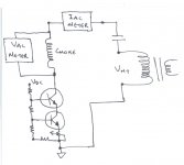
Put the choke vertically in the middle and put the HT supply and CCS in series, then their combination across the choke. That allows you to pass a constant current through the choke. Then add the AC source (the transformer) in series with the capacitor, and connect their combination across the choke. The DC can't go into the AC supply because the capacitor blocks it, and the AC can't go into the HT supply because the CCS blocks it. Both are forced to pass their currents through the choke.
The CCS would be better if it had an LED as the voltage reference from the base down to 0V, rather than just a resistor.

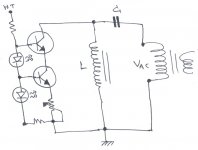
You are nearly there. I would post a diagram, but scanning is a bit tricky at the moment. You need an inverted CCS. That's to say, you need to turn the CCS upside down and replace NPN transistors with PNP transistors. The output terminal can then feed the choke as its path to 0V. Your AC department is fine.

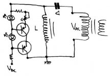
Very nearly. The output of the CCS is the collector of the lower transistor, so this needs to go to the top of the choke. The upper line of the CCS (where the LED joins the resistor) need to go to the positive terminal of the power supply. The lower end of the resistor/LED string goes to power supply 0V and the bottom of the choke.


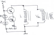

Theoretically, it should be OK for 200mA. The limit is actually determined more by the dissipation in the MJE350 than current limits for the transistors. Suppose you decide to test with 50V AC. You would need to apply at least 100V of HT to the CCS to ensure that it didn't drop out. But if you were passing 200mA, that would mean the MJE250 would need to dissipate 20W (which is its maximum on an ideal heatsink). Moral: Heatsink the MJE350 carefully, and be wary about increasing current beyond 100mA and HT to the CCS beyond 50V.
Hi EC8010,
I am going to agree completely with you on the current vs inductance matter for iron cores. My LCR meter will only generate a 1 Vac signal with very low DC current capacity. I would need to build the jig if I wanted to do this.
Hi resident,
You really have to watch the dissipation as things will get hotter than you expect rather quickly. Don't skimp on the heatsink area. You might want to use a TO-3P package.
-Chris
I'm here to save you from that fate!This has to be the longest thread with only two contributors!
I am going to agree completely with you on the current vs inductance matter for iron cores. My LCR meter will only generate a 1 Vac signal with very low DC current capacity. I would need to build the jig if I wanted to do this.
Hi resident,
You really have to watch the dissipation as things will get hotter than you expect rather quickly. Don't skimp on the heatsink area. You might want to use a TO-3P package.
-Chris
EC8010 said:This has to be the longest thread with only two contributors!

anatech just stopped the fate!
In a few hours I'll know what I have from junk! Now I'm going to buy the transistors. Yup TO-3P package! I'll buy 2 or 3 just to have them. You never now.....
 hehe
hehe- Status
- This old topic is closed. If you want to reopen this topic, contact a moderator using the "Report Post" button.
- Home
- Design & Build
- Parts
- Marconi TF2700 LCR bridge and measuring iron-cored chokes