Anyone has an idea of the circuit for an automatic cooling fan? i mean that it turns on automatically when a sensor reaches certain temp...and i heard there are some that even change speed according to the temp, but i can't find schematics! i found something using tl88, but the datasheet doesn't say much.
hernanstafe said:Anyone has an idea of the circuit for an automatic cooling fan? i mean that it turns on automatically when a sensor reaches certain temp...and i heard there are some that even change speed according to the temp, but i can't find schematics! i found something using tl88, but the datasheet doesn't say much.
I published an article with a 4-speed temp fan control in Audio Amateur, I think early 80-ies. You may want to look it up at www.audioxpress.com .
Jan Didden
Just about as simple as you can get. ")
http://www.diyaudio.com/forums/showthread.php?postid=652993#post652993
edit: I just noticed you want one that turns off, mine is a variable speed one that never actually turns off.
http://www.diyaudio.com/forums/showthread.php?postid=652993#post652993
edit: I just noticed you want one that turns off, mine is a variable speed one that never actually turns off.
Hi hernanstafe
I use 12v cooling fans that operate from a 7812 voltage regulator. Or, if you want it to go slower use a 7809 regulator. I connect a temperature sensor into the fan supply circuit and set the sensor on the heatsink set at around 55 degrees.
I normally use one fan - at least - per heatsink.
I do not think you can get much simpler.
Don

In the temperature triggered circuits, the device has to get hot before the fan turns on. Electronic Design magazine had an article a couple years ago (probably still available on their web site) about a fan speed controller that uses the current drain of the circuit to control fan speed. That circuit speeds up the fan BEFORE the circuit gets hot and thus prevents it from getting hot. Seems like a much smarter way to go to me.
I_F
I_F
I think this is what you are talking about:
http://www.elecdesign.com/Articles/Index.cfm?ArticleID=5695
Pretty interesting design.
http://www.elecdesign.com/Articles/Index.cfm?ArticleID=5695
Pretty interesting design.
blip1882 said:I think this is what you are talking about:
http://www.elecdesign.com/Articles/Index.cfm?ArticleID=5695
Pretty interesting design.
hehe
you can always use thermoswitch for home boilers,with relay for reversing action .......
Originally posted by pinkmouse
Just about as simple as you can get.
http://www.diyaudio.com/forums/show...2993#post652993
edit: I just noticed you want one that turns off, mine is a variable speed one that never actually turns off.
With the thermistor in that position, it needs to be a positive TC, not the NTC shown, or the fan will slow down as the thermistor warms up. And suitable PTC thermistors seem hard to find.
Using an NTC but swapping it over to R2 position, the 317 doesn't seem a good chip for the job - the L200 regulator with its higher multiplier in the output voltage formula
Vo = 2.77(1 + R/Rth)
gives a better response.
cpemma said:
With the thermistor in that position, it needs to be a positive TC, not the NTC shown, or the fan will slow down as the thermistor warms up. And suitable PTC thermistors seem hard to find.
Using an NTC but swapping it over to R2 position, the 317 doesn't seem a good chip for the job - the L200 regulator with its higher multiplier in the output voltage formula
Vo = 2.77(1 + R/Rth)
gives a better response.
You're probably correct about the improvements to the design, (it is a PTC BTW, I must have used the wrong symbol in Eagle, not paying attention...), as I said, I'm a mouse with very little brain.
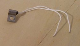
I got a load of screw mount tabbed PTCs from a pile of dead Amcrons, perfect for this application, but I've never seen them in any catalogues.
Attachments
- Status
- This old topic is closed. If you want to reopen this topic, contact a moderator using the "Report Post" button.
- Home
- Design & Build
- Parts
- Automatic Cooling Fan