Ok, I have a big ol' pile of heatsinks from an industrial motor controller that are painted an ugly grey. I realize that the best thing to do, from a performance point of view, would be to strip 'em and leave them "nude", but I have WAF to deal with.
My questions are:
1) Is there a paint designed for thermal transfer?
2)By what factor should I de-rate the sinks painted?
3)Do you think any less of me for considering such a noob blasphemy?
Let the flaming begin
-Casey
My questions are:
1) Is there a paint designed for thermal transfer?
2)By what factor should I de-rate the sinks painted?
3)Do you think any less of me for considering such a noob blasphemy?
Let the flaming begin
-Casey
My question to you would be...What are you planning on using them for?
Also, have you considered having them powdercoated?
If the heat is not "extreme" and you feel like it will not cause that paint to loosen and fall off then you should be fine. I have a couple of chip amps that have painted heatsinks, and they are fine. I did however remove any paint around the area where I mounted the chips.
There is also heat resistant paint (mainly available for grills, etc) that can be found at your local Home Depot, hardware store, etc.
Just my .02 there will be other theories...some will be more precise...
Wayne
The commercial black ones are generally paint (rather than anodised & dyed) so you're in good company.
Strip the old paint off first and use matt black spraycan from a car place (a car in the sun can get too hot to touch). The bare aluminium may need etching or priming to improve paint adhesion and knock-resistance.
If you check IR's AN-1057 there's not much wrong with paint for a passive-cooled sink.
Yes, I wouldn't paint the semiconductor mating surface.
Heatsinks are usually anodised, you better check if it really is paint as anodising is not easy to strip off.
If it is paint and you can strip it off, you will first need to prime the alloy with etching primer. Normal primer will simply fall off after a while. Then on top you use whatever paint you like. Normal car paint should be fine as the heatsinks should never be hotter than the hand can stand.
By painting I think the thermal efficiency would be reduced by a similar amount to that when a mica washer is used.
Oh yes, nude heatsinks are not the best thermally speaking, matt black is the most efficient colour to get rid of heat.
Heat escapes from a heatsink via photons and they don't much care about the color of the heatsink. To absorb heat use flat black color but to get rid of heat plain old aluminum is fine.
I found some auto bumper/trim flat black spray paint that is self etching and works great on bare aluminum. I can't tall any difference in the efficiency of a sink that has a thin coat of spray paint over one that is bare.
I found some auto bumper/trim flat black spray paint that is self etching and works great on bare aluminum. I can't tall any difference in the efficiency of a sink that has a thin coat of spray paint over one that is bare.
Well slap my a** and call me Nancy
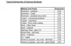
I read the application note by IR that cpemma linked to (table attached), and according to them, paint is more effective than anodizing
Seems this old fart can still learn something
The "bumper paint" seems to be the ticket, though I'll do a mild acid (vinegar) wash first.
Thanx guy's.
-Casey
I read the application note by IR that cpemma linked to (table attached), and according to them, paint is more effective than anodizing
Seems this old fart can still learn something
The "bumper paint" seems to be the ticket, though I'll do a mild acid (vinegar) wash first.
Thanx guy's.
-Casey
Attachments
I don't think standard commercial anodizing is thick enough to prevent shorts caused by tiny bumps or burrs. Those aluminum TO-3 insulators you see are hard anodized with thicker than normal anodizing.Narcisse91 said:Strip the paint and have them anodized.
Use the anodizing as your insulator, and you can use non-insulated components, lowering your overall thermal resistance, improving cooling.
I think that will get you better results than picking the perfect paint.
Even if you measure carefully for shorts there is little guarantee that shorts won't develop later as the parts grow and shrink with heat cycles.
It's just my opinion, but I'd be very carefull with this idea.
I'm not sure of different levels of anodization and where the each one reaches it's limits - definitely something to consider - but a shop that does the anodization should know this. I know some will withstand a couple thousand volts before they break down, higher than most FETs will be operating.
Using anodization as an insulation suffices in commercial, industrial and even military applications (the most particular when it comes to long term durability), so for a home project, I would think it would be fine.
When you anodize, you actually embed the material down into the aluminum. So any shorts that would develop would have to go through the thickness of the anodized material.
One of my next amps is going to be built in a chassis that was designed to hold FETs this way, using just metal clips to hold fets against an anodized surface.
But hey, it's at your own risk, so if you're not comfortable with the idea, don't do it.
Hi,
that table in post8 is worth reading.
Heat gets out of the sink in two ways:
radiation and conduction.
Conduction to the laminar layer of air in direct contact with the surface accounts for the majority of the dissipation capacity of a heatsink.
The faster the air travels past the sink the thinner the laminar layer. A passive cooler has slow air flowing past the surfaces (that's why it's important to have the major dimension of the sink fins in a vertical direction) resulting in a thick layer and we all know that air is a poor conductor of heat. Blow the sink and dissipation improves markedly, even a slow blower or a strong draught makes a significant difference.
Radiation accounts for less than 10% of the dissipation capacity of a passive heatsink that has been designed to expose a large surface area to the cooling air. A fan blown sink relies on only a tiny proportion of it's dissipation capacity from radiation (probably less than 2% or 3%).
Radiation can be improved by choosing a high emissivity surface.
The gains in emissivity from 0.7 to 0.94 are significant PROVIDED that the conduction is not compromised. Adding a thick layer of insulating coating will reduce conduction and since this should account for at least 10 times the radiation then take care with any added insulation.
A gain of 2.7% in radiation [(0.94/0.7-1)*8%] and risking the loss of 10s of percent in conduction should be approached cautiously. Plastic coatings (dipped or electrostatic) can be very thick, undercoat adds to thickness, brushed on coatings are usually thicker, etc.
Why are the fanned CPU coolers almost always plain aluminium? Because the sink relies on about 99% of it's capacity from conduction through the very thin boundary layer and the fast moving airflow that carries away the heat (turbulence is the computer chips friend, that's also why they are so noisy).
The gains in emissivity from 0.7 to 0.94 are significant PROVIDED that the conduction is not compromised. Adding a thick layer of insulating coating will reduce conduction and since this should account for at least 10 times the radiation then take care with any added insulation.
All true, the question would seem to be, how much does anodizing compromise conduction? It is basicaly a ceramic (aluminum oxide) that is "grown" on the surface through a electro/chemical process. The thickness is the issue with both, but I would think that if the thickness were equal, paint would have the edge over ceramic..it would be hard getting paint as thin as an anodized layer though.
-Casey
P.S. It was post 6, not 8
Hi,
the anodise layer is thin, 0.1thou (=0.1mil=0.0025mm) or so.
It is also a good thermal conductor and electrical insulator and pretty tough (but hard and therefore brittle). Have you tried to deliberately remove it?
Aluminium oxide is the electrical insulator used to isolate power packages from their heatsinks and even though 20times thicker than mica still performs better. Shame about the high cost and the brittleness.
Aluminium oxide (abrasive paper) is also used as a harder (=longer lasting) alternative to glass paper.
Repeat twenty times "I must learn to read, I must learn......... to read"
Anodisation is superb-easy to remove with strong caustic like 10% NaOH (easily availlable in every supermarket as a drain opener/cleaner)richie00boy said:Heatsinks are usually anodised, you better check if it really is paint as anodising is not easy to strip off.
the anodise layer is thin, 0.1thou (=0.1mil=0.0025mm) or so.It is also a good thermal conductor and electrical insulator and pretty tough (but hard and therefore brittle)....Aluminium oxide is the electrical insulator used to isolate power packages from their heatsinks and even though 20times thicker than mica still performs better.
So ceramic conducts heat better than volcanic glass...enamel conducts heat better than either. I don't have one here to measure, but I would wager your average mica insulator is considerably thicker than .005 mil (.1/20), at least the ones I've dealt with in the last 25 years.
Have you tried to deliberately remove it?
Repeat twenty times "I must learn to read, I must learn......... to read"
 WOW!
WOW! If you had read my post that started this thread, you would know that ..A) The heatsinks were painted..not anodized..when I got them, and..B) I was under the impression that anodized was superior to any other surface in all circumstances as well..by reading I learned that this is not the case. If you know something that the industry giants, such as International Rectifier, and acomplished audio engineers like Rod Elliot ( link to his heatsink spread sheet here ) then by all means share. If not, then perhaps you should heed your own advice and read the documents linked in this thread.
-Casey
Hi Valve,
I'm not having a dig at you nor putting you down.
Heatsink insulators made of aluminium oxide are about 2.5 to 4mm thick. That's where my 1/20 came from. It could be as bad as 50 to 60 times thicker and yet they still perform better than mica insulators.
Finally, the topic is painting and all I was pointing out is that paint will reduce the effectiveness of the major dissipation route of a heatsink.
If you decide that the emissivity is important enough to be worth striving for, just take care not to cripple conduction.
I'm not having a dig at you nor putting you down.
is a reference to me misreading posts6/8 and giving the wrong reference.Repeat twenty times "I must learn to read, I must learn......... to read"
P.S. It was post 6, not 8
Heatsink insulators made of aluminium oxide are about 2.5 to 4mm thick. That's where my 1/20 came from. It could be as bad as 50 to 60 times thicker and yet they still perform better than mica insulators.
Finally, the topic is painting and all I was pointing out is that paint will reduce the effectiveness of the major dissipation route of a heatsink.
If you decide that the emissivity is important enough to be worth striving for, just take care not to cripple conduction.
'm not having a dig at you nor putting you down.
is a reference to me misreading posts6/8 and giving the wrong reference.
My bad

Sorry for getting so snippy with you..It's 3:00 am here, and I'm still up with sick grandbabies (twins)..not a real mood enhancer.
I think you can see how I could have taken it wrong though.
I hope there's no hard feelings.
-----------------------------------------------------------------------------------
Back to heatsinks..
Before I started this thread I would have argued myself blue that anodizing was the only viable option..I'm as stunned as anybody that paint, thinly applied, would in any way actually out perform anodized. I started this thread fully expecting to hear I would have to double the heatsink size if I were foolish enough to paint it.
-Casey
fwiw -- the urethane finish on a bar-top is probably 20 mils thick. powder coatings range from 1 to 40 mils.
the insulation on an LM3886TF is 1 mil (i.e. the thickness of an LM3886 is 176 mils, while the LM3886TF is 178 mils so divide the difference by 2) and, not accounting for a mica washer on the "T" variety, it requires a heat sink with a thermal impedance an entire 1 C/W lower to allow the same heat removal.
the insulation on an LM3886TF is 1 mil (i.e. the thickness of an LM3886 is 176 mils, while the LM3886TF is 178 mils so divide the difference by 2) and, not accounting for a mica washer on the "T" variety, it requires a heat sink with a thermal impedance an entire 1 C/W lower to allow the same heat removal.
fwiw -- the urethane finish on a bar-top is probably 20 mils thick. powder coatings range from 1 to 40 mils.
the insulation on an LM3886TF is 1 mil (i.e. the thickness of an LM3886 is 176 mils, while the LM3886TF is 178 mils so divide the difference by 2) and, not accounting for a mica washer on the "T" variety, it requires a heat sink with a thermal impedance an entire 1 C/W lower to allow the same heat removal.
I figure that the paint thickness would have an affect on the heatsink's performance ( I have to believe the folks that drew up the table of different coatings figure this as well..I accept this. Unfortunately I can only find vague references to “keep the paint thin”, rather than “de-rate by x% for every x mils of thickness”). My only option is to make sure the projected deg.C/W of the sink is less than needed...by how much is a guess. Another thing to consider (i think), is that the conduction of the material mating the relatively tiny contact area of the device to be cooled is way more critical than the material mating the sink to the slow moving air in a convection cooling arrangement (insulator in series, sink area in parallel?).
I do have the sinks to compensate however
...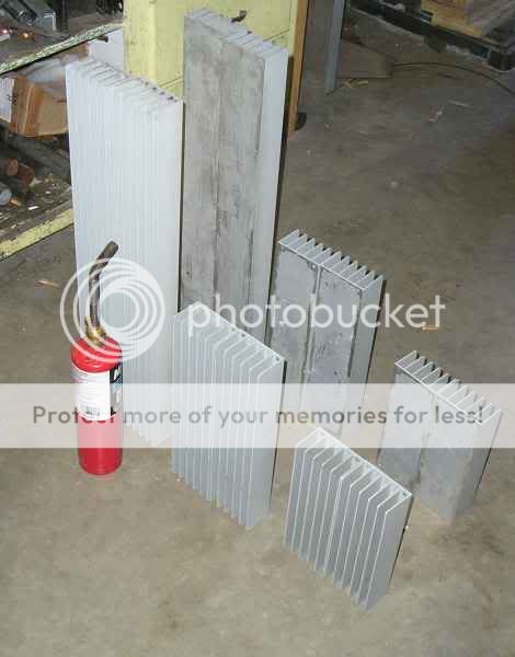
I pulled these off an industrial VFD motor controller. I plan to use 2 sets of 4 sections 8” long per channel (ala Krell). According to the heatsink spreadsheet I linked above, each set will have a thermal rating of .21 deg.C/W, for a total of .105 deg.C/W per channel..this aint gonna be a “cute” chip amp
 .This “extreme” overkill doesn't seem so extreme when you consider I plan running the chips in my BPA200 at +/- 35V (pretty universally excepted as the best sounding voltage on the chip). The “normal” approach is to reduce the rails when bridge/paralleling to keep the chip from overheating. I want the sinks to keep the chips as cool as possible, even under these harsh conditions.
After seeing your huge turntable project i would think WAF was a very minor concern for you
There is little doubt that Lorelle is more indulgent than most when it comes to my gear, but it can't be ugly. My chart shows that tolerance to size is directly proportionate to it's overall aesthetic..it can be big as long as it's “pretty”
.-Casey
Hi,
you have a bigger problem than choosing between paint or bare aluminium.
The backplate of those sinks is thin.
A single device bolted near the optmum position (40% up from the bottom) will not heat the whole back plate evenly.
The sink will not get near the manufacturer's disspation which allows for the whole back plate at the same contact face temperature.
The usual rule for fairly even temperature spread is the radius from the device should be <=10*thickness.
The other de-rating factor to take account of is the deltaT reduction. DeltaT is the difference between the contact face temperature and ambient temperature of the cooling air.
Taking the thin backplate and the deltaT in account I suspect 0.21C/W may go up to about 0.4 to 0.5C/W.
Increasing the height will not gain much since the remoteness of the extra fins from the heat source means the fins run very cool and as a result don't dissipate much in comparison to the fins directly behind the chipamp contact face.
Sorry to have to disappoint.
Good sinks cost good money.
Now, if you were to build a discrete amplifier and distribute the devices to maximise the effective heat distribution, then you would be back in business.
- Status
- This old topic is closed. If you want to reopen this topic, contact a moderator using the "Report Post" button.
- Home
- Design & Build
- Parts
- Painting Heatsinks..I Know..Bad Idea