I was hoping to get some help understanding the audio section of my cd player. I have the schematic, attached (it's a Meridian 506.20). I'm not that knowledgeable on electronics, so please bare with me..
I don't understand what's going on with the opamp (5534) for each channel. I'm told the transistors at the output are a push-pull amplifier, but what's the integrator circuit for on the left (LF353)? where does the -ve input labeled "right" come from? Is it the output of the push-pull amp? and if so, i have no idea what all this feedback is doing
thanks for any help!
Attachments
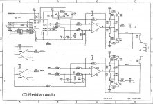
graemechambers said:what's the integrator circuit for on the left (LF353)? where does the -ve input labeled "right" come from? Is it the output of the push-pull amp? and if so, i have no idea what all this feedback is doing
"Right" and "Left" are indeed outputs of push-pull stages. Integrators on LF353 are making what is called "servo" feedback, reducing DC offsets at the outputs. I hope this helps.
graemechambers said:thanks guys, I think I understand.
I'm still a bit confused as to why everything is fed back into the 5534 though. I thought the push-pull amp was there only to boost the output of the 5534?
Well it is, but by injecting an error correction (DC Servo) into the opamps, you can correct any offset from the final stage.
Dont think audio, think DC as the intergrators really have nothing to do with the audio portion. Lets say the final output has some DC offset, this is after the opamp and after the push pull stage.
By taking that DC offset from the output and injecting it back into the opamp inverted, that drives the opamp in the opposite direction the same amount as the offset effectivly nulling it back to zero.
They do this to avoid having to use a capacitor to block DC from the output.
Zc
Hi,
the 5534 opamp is amplyfing the signal. It is set up as a DC coupled amplifier and so sends it's own output offset and five times any input offset to the receiver.
The push pull is a buffer, it is providing extra current to drive any sensible load. I think this circuit will drive 600ohm Zin.
The 353 is a DC servo, to cancel out most of the DC and extremely low frequency AC signals that otherwise could be present on the output.
There are a couple of modifications you could make to improve the DC servo.
Go to diyhifi.org and read the DC servo thread.
A filter on the input to the 353 eases the work it has to do and thus improves performance.
A filter on the output of the 353 reduces noise injected into the 5534 inverting input.
All four opamps could be replaced by higher performance devices and even by an all discrete opamp on a piggy back board.
RE:Understanding schematic
Hi-Definetly replace the op-amps. My preference is the AD825 which is very musical . You can obtain these on EBAY from a seller identified as ca2832. Use the advanced search tool. Although he is located in Australia ,he ships to the US quickly and for little money. The other common modification is in the power supply . Generally higher quality capacitors are installed often bypassed with quality film units. I have done this and it proved much easier than would would imagine. Good Luck.
Hi-Definetly replace the op-amps. My preference is the AD825 which is very musical . You can obtain these on EBAY from a seller identified as ca2832. Use the advanced search tool. Although he is located in Australia ,he ships to the US quickly and for little money. The other common modification is in the power supply . Generally higher quality capacitors are installed often bypassed with quality film units. I have done this and it proved much easier than would would imagine. Good Luck.
- Status
- This old topic is closed. If you want to reopen this topic, contact a moderator using the "Report Post" button.
- Home
- Design & Build
- Parts
- help understanding a schematic