Hi
Found EXpressPCB so easy to use and very good, but tried to print to printer drivers etc to overcome its lack of printing cooper layers.
Ive now found a program KiCad http://kicad.sourceforge.net/en/download.shtml
does anyone use this on windows at least.
It looks very professional but at the moment i cant even stick a pad down. Guess its the help file i need to read. I assume you can make PCB's without having to create the Scheme and then do an auto generation.
Regards
John
P.S Getting back into DIY electronics/Audio after 15 years and finding I could have designed the PCB by hand like the old days! by the time I find an easy and free(ish) computer program.
Depending on you needs, you might be able to use the free version of eagle from www.cadsoftusa.com.
I have the Pro version, as I got tired of the limits set in the different low cost versions.
Maybe a group order for eagle or other layout program licences is an option to get the price down?
\Jens
I have the Pro version, as I got tired of the limits set in the different low cost versions.
Maybe a group order for eagle or other layout program licences is an option to get the price down?
\Jens
Eagle is based on a workflow from schematics -> PCB -> Gerber + drill files.
You can however make your PCB directly in the PCB editor, you just need to create a netlist first. This is done by adding connections from pad to pad on the parts you have placed.
I find it better to first create a schematic and the the PCB, it also makes it easier to not make connection mistakes.
\Jens
Hi
I can't use eagle because its the free version only that i have tried but it only allows for really small PCB sizes but does seem very good.
Will have to see what price an upgrade is, in English pounds. Main problem is I am getting back into PCB/Audio making etc becuase i am on long term sick at the moment (and hence the time but not the money - bloody typical isnt it)!.
Regards
John
I have looked through the Kicad documents now, and I feel this is the program for me. One problem remains - I have spent tens of hours designing all the componentes I need in Eagle, and I want to convert these to Kicad. Is there any known way of doing this besides redrawing every single library component?
JensRasmussen said:For prices go here: http://www.cadsoftusa.com./prices.htm
Don't forget the "Not for profit version" (same as Standard version but a fraction of the price as it's for non-profit/personal use only):
http://www.cadsoftusa.com./nonprofit.htm
(not widely advertised...)
Howdy stottie & zilog,
Kicad does have a learning curve. In my experience, it functions much like any other vector drawing program. But not so much like the popular "free" versions designed to get your board making biz.
I'm using the 7-JAN-2006 release and there is probably a newer version.
You can run any of the individual programs stand alone, and on a network. Never had it freeze on my PC, but that's maybe 'cause it runs on a dual 1 Gig Xeon processor with 4 gig of memory.
pcbnew.exe is the drawing program and you can treat it kinda like you were just hand drawing the traces. Being an old guy who hand drew boards before the computer revolution, it's not a problem. Personally got no use for those auto-router functions and many folks find it is not as good a method for parts placement as your brain. But the auto-router function is included if you're so inclined. No need to create any netlists etc. to use this program. Create gerber files or just print out your results to any drawing program, Photoshop, Corel Photo Paint, etc.
One small disclaimer on printing. The program has or had an accuracy problem about printing exactly what you want to the correct size. Work around: get the free version of PDFCreator and set it up for the resolution you want for .jpg, .tif, .bmp, .pdf and so on. To use the print icon, click on it, select all the check boxes you want, choose "Accurate Scale 1", single page, click on print, choose the PDFCreator as the printer and go. This will generate an image suitable for a laser printer type iron down board. Don't forget to convert the image to black and white. Your file size will drastically reduce in size.
The component library has a good sized list of pre-drawn parts. But you can and may wish to modify them for your own purpose. Yes, you can create your own custom parts and save them in the library.
You can create your own parts specifically for the project at hand in its own library with names of your choice without fubaring the main one.
No, you can't import other parts libraries to my knowledge.
As with all programs, there are some quirks one must learn. This is "open source" freeware after all. There is a Kicad users forum, but mostly talk about implementing on Linux and not much help with actually using it.
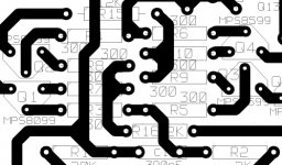
Here's a low res small piece of a much larger board.
HTH
Kicad does have a learning curve. In my experience, it functions much like any other vector drawing program. But not so much like the popular "free" versions designed to get your board making biz.
I'm using the 7-JAN-2006 release and there is probably a newer version.
You can run any of the individual programs stand alone, and on a network. Never had it freeze on my PC, but that's maybe 'cause it runs on a dual 1 Gig Xeon processor with 4 gig of memory.
pcbnew.exe is the drawing program and you can treat it kinda like you were just hand drawing the traces. Being an old guy who hand drew boards before the computer revolution, it's not a problem. Personally got no use for those auto-router functions and many folks find it is not as good a method for parts placement as your brain. But the auto-router function is included if you're so inclined. No need to create any netlists etc. to use this program. Create gerber files or just print out your results to any drawing program, Photoshop, Corel Photo Paint, etc.
One small disclaimer on printing. The program has or had an accuracy problem about printing exactly what you want to the correct size. Work around: get the free version of PDFCreator and set it up for the resolution you want for .jpg, .tif, .bmp, .pdf and so on. To use the print icon, click on it, select all the check boxes you want, choose "Accurate Scale 1", single page, click on print, choose the PDFCreator as the printer and go. This will generate an image suitable for a laser printer type iron down board. Don't forget to convert the image to black and white. Your file size will drastically reduce in size.
The component library has a good sized list of pre-drawn parts. But you can and may wish to modify them for your own purpose. Yes, you can create your own custom parts and save them in the library.
You can create your own parts specifically for the project at hand in its own library with names of your choice without fubaring the main one.
No, you can't import other parts libraries to my knowledge.
As with all programs, there are some quirks one must learn. This is "open source" freeware after all. There is a Kicad users forum, but mostly talk about implementing on Linux and not much help with actually using it.
Here's a low res small piece of a much larger board.
HTH
Attachments
OK, Kicad sounded interesting, so I downloaded it. However, it seems to be as strange and awkward as other pcb programs, just in a different way. One has to speak french english, for instance. ")
One thing that has got me stuck immediately is how to connect two component pins? That should be about the most basic thing one can do, but I cannot figure out how to do it. That is, I have figured out a way, but that is so awkward that I refuse to believe that is how to do it. If I start a track at a pin and try to end at another pin (of the same or another component), I am not allowed to end the track. The only way I can find of doing this is to first start a track from the first pin and create a via somewhere to end the track. Then I start a new track from the other pin and let this track overlap or intersect the first track and then create a new via to end this track. Then I can erase the two vias and any unwanted track segments, and if I am lucky, it doesn't erase any other track segments. I have tried to explicitly create vias at the pins, but that doesn't work either. I am sure you others must have found out how to do this, or you wouldn't even have suggested the program, so what's the secret?
One thing that has got me stuck immediately is how to connect two component pins? That should be about the most basic thing one can do, but I cannot figure out how to do it. That is, I have figured out a way, but that is so awkward that I refuse to believe that is how to do it. If I start a track at a pin and try to end at another pin (of the same or another component), I am not allowed to end the track. The only way I can find of doing this is to first start a track from the first pin and create a via somewhere to end the track. Then I start a new track from the other pin and let this track overlap or intersect the first track and then create a new via to end this track. Then I can erase the two vias and any unwanted track segments, and if I am lucky, it doesn't erase any other track segments. I have tried to explicitly create vias at the pins, but that doesn't work either. I am sure you others must have found out how to do this, or you wouldn't even have suggested the program, so what's the secret?
Hmm,
Sounds like you're trying to use Pcbnew.exe.
On the top left side of the program window, under where you see the white box with "track xx.x" is an icon with what looks like a magnifying glass and a red check mark is what's called the DRC. Click it to change to the "on" state. Now you can draw a trace anywhere on the page.
The start up value is always "off". So you must set it every time you start the program.
If you downloaded the entire program for Windoz, there is a help manual for every program under the heading Help. Admittedly it is more than somewhat lacking in detail. Things like ending a track where you want, making a bounding box, deleting unwanted traces or parts, adding text, moving a placed part, copying, flipping, rotating, whole blocks and on and on. Remember to check out what the right mouse click does for many functions.
For instance, find the add tracks icon on the right side of the window.
Right click and you can now set trace width, vias etc. Now draw a trace any length by left click and move the mouse. When you get to where you want, release the left click and now right click to open up a new dialog box with choices. This is the method for many functions.
Kicad has a serious learning curve, maybe a steep one for many folks. I found most other pcb creation software also has a learning curve and few are intuitive. At least IMHO.
The price is right for many people. But your time is also important and has a real value. My granpa always said, "Nothing succeeds like perseverance". Followed by "Gitr done boy.".
HTH without discouraging too much.
acenovelty said:
On the top left side of the program window, under where you see the white box with "track xx.x" is an icon with what looks like a magnifying glass and a red check mark is what's called the DRC. Click it to change to the "on" state. Now you can draw a trace anywhere on the page.
The start up value is always "off". So you must set it every time you start the program.
DRC was the problem. As I noted in my second post, I eventually found the problem by trying to switch various options on and off to see if any of them made a difference. I suppose DRC serves a purpose, but it is very confusing since it is still possible to lay tracks, just very restricted. If it turned off track laying entirely it would have been easier to realize that some mode or option must be wrong.
If you downloaded the entire program for Windoz, there is a help manual for every program under the heading Help. Admittedly it is more than somewhat lacking in detail.
Yes, I know, but it didn't really say much about DRC, and before knowing that was the problem I wouldn't even have known what to look for anyway. It seems though that the help is somewhat more extensive than it seemed at first sight. The help reader confused me first so I missed large parts of the manual.
Kicad has a serious learning curve, maybe a steep one for many folks. I found most other pcb creation software also has a learning curve and few are intuitive. At least IMHO.
Yes, I agree that most programs seem awkward and illogical. I have tried Eagle and a few others, but gave up rather quickly, since it seemed like programs I thought I could never stand anyway, and I hate to waste a lot of time to learn a program just to find out that I don't want to use it. Also, for the commercial programs, there are the various limitations for the free version, making it even less interesting to put too much effort into learning a program that may anyway not be sufficient in some cases.
It seems one has to learn to think in a certain way to get used to most commercial and similar programs (including some free ones like Kicad). Maybe there is a reason for some of the awkwardness or maybe it is just a consequence of various historical reasons.
Anyway, having grasped the basics of board layout with Kicad, I think this might be a program I can learn to live with and find more useful than painful. Not the least since it is quite possible to just layout a board without having a netlist or anything, and since there is no limitation on board size etc. It will take some work to fix the worst omissions in the module library, though (or just forget about that too and layout some components as a bunch of single pads).
So thanks for the recommendation. I think Kicad is the first board layout program that is on my computer to stay (apart from MS Paint, that is
).Howdy Christer,
Hope you are able to make Kicad work for your projects.
One quirk that I've not been able to resolve is updating the software when a new release is published. Seems that "my" library and the master one gets overwritten with the newer version. Does not make for a happy camper when many hours have been spent creating some special versions of a common part for a specific project.
Fortunately, the programs run from the .exe files as stand alone units if desired. You can easily burn the entire program to a CD and take it anywhere.
Regards
acenovelty said:
One quirk that I've not been able to resolve is updating the software when a new release is published. Seems that "my" library and the master one gets overwritten with the newer version. Does not make for a happy camper when many hours have been spent creating some special versions of a common part for a specific project.
Since I have just installed it, I haven't run into any update problems yet. However, that is hardly a surprising problem, and a problem one encounters frequently with many programs of different kinds.
I would think the best solution is not to modify the existing libraries, but to put all new modules in one or several new libraries. Unless the distribution suddenly starts using new libraries with the same names as you have choosen, they should presumable be safe from being overwritten when updating. However, one should always make sure to have at least one backup copy. Apart from general backups, I think it may be a good practice to either install the new distribution in a new directory (and then copy your own libraries etc.) or, perhaps simpler, make a copy of the whole Kicad installation just before updating it.
stottie said:
Anyway im stuck at placing a PAD for examle! Guess its good and free so must need at least need some learning curve.
You mean you want a single pad without placing any particular component? There is the 1PIN module, but that places a pad with a very big hole. For an ordinary sized pad, you can place a PINTST (presumable intended for a test pin).
If you want you could create a new module, called PAD or whatever, by copying the PINTST and change the relevant text field and save it as a new module.
"copy of the whole Kicad installation just before updating it",
Done that. Now when copying the old library into the new upgrade, the modded parts must be placed in a bogus project before they will appear in the old project. Kinda like you have to use them first and then it works OK. Bummer.
Since my current version works just fine, I see no reason to upgrade for some minor change that provides a function that I won't use.
acenovelty said:"copy of the whole Kicad installation just before updating it",
Done that. Now when copying the old library into the new upgrade, the modded parts must be placed in a bogus project before they will appear in the old project. Kinda like you have to use them first and then it works OK. Bummer.
Well, as I said I haven't tried any upgrading yet, but there seems to be some quirks with defining new modules. I still haven't quite understood when it works and when it doesn't. The various text fields and the names used when saving modules etc. still seems like a mess to me. Maybe there is some clear definition of them in the help files, but I don't think so. Also, if you define a new module and save it into a library while working on a board, you must temporarily delete the library from list of preferences and then add it again. Otherwise it won't show up. However, that is not very surprising and similar things exists in a lot of software. It could be solved if the y wanted to though, and it would make it easier to define new modules.
Since my current version works just fine, I see no reason to upgrade for some minor change that provides a function that I won't use.
The lastes version that seemed to be a stable version that I found was from August this year. There was a December version too, but that was labelled RC1 and is thus probably not considered a stable version.
- Status
- This old topic is closed. If you want to reopen this topic, contact a moderator using the "Report Post" button.
- Home
- Design & Build
- Parts
- PCB programs