Hello
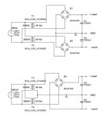
I bought two transformers 220v to 24v (300VA) for a symetric PSU, please look at the attached image.
I want to use it for a five chanel amp with 5x LM3886 gainclones (5x 68W).
According to the type P=V*I, for 8 ohm load and 68W the result is I=2.91amp and V=23.3volt.
My question is if this current is divided to both sides (+-) of the PSU (1.45amp from each rail) or if this current should be available to both rails (2.91amp each).
If this current should be available from each rail then i need a total of 14.55amp from each transformer which means that two 300VA (300/24=12.5amp) transformers are not enough to feed a 340W amplifier (5x68W).
On the other hand the second schematic with one bridge (center tap) seems to share the load current to both transformers since both windingd work all the time for both rails.
I'm confused and either my calculations are wrong or i need much bigger transformers for the 2 bridge desigh than the one bridge design .
Thank you
Alex
Attachments
Hi,
firstly the VA requirement for a good PSU.
Maximum output power is 5 * 68W=340W.
VA=1.5*max Watts=510VA. Your chosen transformers are just about right and you have a little to spare.
The voltage of 24Vac is the loaded voltage for the secondary and it is only obtained IF the input voltage matches the specification.
What is your tolerance on mains supply voltage?
Your PSU voltage will be a bit higher (probably about 6% to account for the regulation of the 300VA transformers).
The two transformewr are probably bi-fillar wound and IF you were to connect them in parallel then connecting the pair of windings on one transformer is the better way to do it.
However, I recommend that you build a separate PSU for each amplifier rather than a big combined one. I believe that the amps perform better that way.
Connect five single rectifiers to the pair of parallel connected transformer secondaries (your lower diagram but with one dual wire from each transformer) and use the spare dual middle wires as a centre tap joined and then taken to the floating audio ground.
From each rectifier connect your pair of dual polarity smoothing caps.
BTW.
I don't agree with running long speaker cables around the room from a 5channel amplifier.
I would locate the amplifiers where they are needed and run long interconnects to the smaller amplifiers.
I run a stereo system and I keep the amps right next to the speaker terminals The cables including INSIDE the speaker are less than 3feet long. Better perfomance and less cost.
Thank you for your answer but my main concern is what happens with the current.
I think that when you have two bridges and you connect a load to the plus rail only then one transformer gives all the current to the load, on the other hand with one bridge both transformers give half (each) of the load current.
If this is true and the load is an amplifier with a sinus input signal using both rails to output 100w then both transformers have to be able to provide 100W (each for half of the input signal period)while with one bridge both transformers have to provide 50W becaust htey supply current to both rails (these are simplified numbers without losses)
Thank you
Alex
Hi,
you are not working with sinusoidal waveforms in a capacitor input power supply.
The maths is more than a little complex and I for one would not try to estimate manually how big or low the real currents are that flow in the transformer. I cheat and use PSUD2.
Download a copy and learn to use it.
The overall calculation I gave earlier is usually sufficient to ensure no overheating and good amplifier performance.
Some will say the transformer is too big. Believe who you want after you have built a selection to prove the case one way or another for yourself.
Hi AndrewT
My mains is quite stable so no problem, I couldn’t find a center taped transformer (2x24 secondary) so I bought 2 single transformers. (steel core not toroidal) and this is why I have the choice (and problem) of using one or two rectifier bridges.
The output of each transformer is 24.31v without load and the psu will be without stabilization but with dedicated bridge(s) and capacitors for each channel.
The diodes will not be the ones shown in the schematic and the capacitors will be 2x4700u for each rail of each channel
Best regards
Alex
AndrewT said:Hi,
you are not working with sinusoidal waveforms in a capacitor input power supply.
The maths is more than a little complex and I for one would not try to estimate manually how big or low the real currents are that flow in the transformer. I cheat and use PSUD2.
Download a copy and learn to use it.
The overall calculation I gave earlier is usually sufficient to ensure no overheating and good amplifier performance.
Some will say the transformer is too big. Believe who you want after you have built a selection to prove the case one way or another for yourself.
Can you please tell me if the result with two bridge will be the same as with one bridge, i mean if the current to the load will be enough for full output in both cases?
Alex
Hi,
the transformer limited output current from both arrangements of the bridges will be the same.
Each 300VA 24Vac can provide a continuous DC current to your load of about 6.25Adc. This is for paralleled secondary windings. Each winding can support 3.1Adc.
With both transformers wired up as either centre tapped or separate secondaries the total continuous output will be +-6.25Adc to the dual polarity supply.
The major differences between the dual rectifier and the single rectifier are the current the rectifier can operate at and volts drop. The dual rectifier gets more of a rest and can handle about double the current that the single can do (at least that's what the proponents of the dual arangement claim).
The disadvantage of the dual is the extra 1.4V of diode loss compared to the single.
Go do the single rectifier and save the cost of five rectifiers and five sets of RC snubbers (that's twenty caps and twenty resistors).
For a 67.8Vdc supply to lose 2.8v rather than 1.4V is a significant loss.
I do not believe there is any advantage one way or the other with regard to isolating hum or ripple from the load.
AndrewT said:
Each 300VA 24Vac can provide a continuous DC current to your load of about 6.25Adc. This is for paralleled secondary windings. Each winding can support 3.1Adc.
With both transformers wired up as either centre tapped or separate secondaries the total continuous output will be +-6.25Adc to the dual polarity supply.
Hi
The two transformers i have are both wiith a single secondary winding (like the ones in the schematic, one primary winding and one secondary) and to make the center tap psu i have to use the secondary's of 2 seperate tranformers connected as shown in the second schematic.
I don't know if this changes anything about the current calculation.
About the transformer current, you say that each 300VA transformer can provide 6.25Adc but according to P=V*I=>I=P/V the current should be 12.5A, you probably mean a 2x24vac transformer with gives 2x6.25A or 12.5 for paralleled secondary windings.
Thank you
Alex
Hi,
300VA 24Vac is 12.5Aac.
BUT they CANNOT do 12.5Adc after a capacitor input filter.
one 300VA 24Vac can do a continuous 6.25Adc after a capacitor input filter.
One pair of 300VA (total 600VA) 24-0-24Vac can do a continuous +-6.25Adc in a dual polarity PSU, fed through one rectifier.
300VA 24Vac is 12.5Aac.
BUT they CANNOT do 12.5Adc after a capacitor input filter.
one 300VA 24Vac can do a continuous 6.25Adc after a capacitor input filter.
One pair of 300VA (total 600VA) 24-0-24Vac can do a continuous +-6.25Adc in a dual polarity PSU, fed through one rectifier.
- Status
- This old topic is closed. If you want to reopen this topic, contact a moderator using the "Report Post" button.
- Home
- Design & Build
- Parts
- One or two bridge PSU