The attachment is my current meter which want to use at high voltage and low voltage as well.
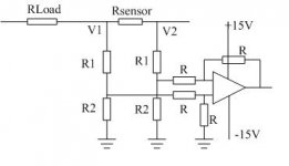
I use the Rsensor and test the voltage on the resistor. Due to the high voltage(V1V2), so I add a voltage divider to get a low voltage input to the differential amplifier. Because the current I want to test is very small, about several hundred nA. So I don't want the current go through the divider is too high. The R1 must be very high(~several G Ohm). And the ratio between left and right R1/R2 should also be the same.
So is there some other solution about the current measurement? And is anybody know how the ammeter works and its schematic?
Thank you very much!!
Attachments
")
Hi,
you almost have a bridge circuit there.
Why reference it to earth?
Collect all the 0volt references together and float them to an opamp reference and make the supply to the opamp float with the measuring reference.
Then you can work at any voltage within the insulation range of the equipment.
But, why all the complcation?
Just measure the voltage drop across the sense resistor.
- Status
- This old topic is closed. If you want to reopen this topic, contact a moderator using the "Report Post" button.
- Home
- Design & Build
- Parts
- need help about ammeter