i have some questions about this schematic....
can you please tell me what the components labeled #1, 2 and 3 are ?
I'm an electronics newbie.
Also, what is the component located just to the right of the power input plug? It looks like a Cap in a box.
Thanks for all your help
-maz
can you please tell me what the components labeled #1, 2 and 3 are ?
I'm an electronics newbie.
Also, what is the component located just to the right of the power input plug? It looks like a Cap in a box.
Thanks for all your help
-maz
Attachments
question
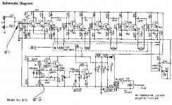
This is an intriguing schematic!
#1 is the input RCA, that one's easy.
#3 is a neon stabiliser; think of it as the tube version of a zener diode, except that it's threshold voltage collapses if it ignites..
#2 is a set of 4 LDRs (light dependent resistors) in a light-tight enclosure with a lamp. (The CdS means Cadmium Sulphite Cell, a LDR type). The lamp current determines the light level and therefore the resistance of the LDRs. That in turm controls the volume level in the four amp stages. The schematic part with the neon is an oscillator, that flashes the light and generates a vibrato effect. Look to the right: there is a selection switch selecting either vibrato (the controlled chain) or chorus.
The component to the left of the plug is an auxiliary mains socket for an extra piece of gear.
Seems this is a guitar amp or effect unit or something?
Jan Didden
wow! very impressive, janneman!
It IS in fact a guitar / instrument effect pedal. This one simulates the rotary speaker sound of a Leslie Speaker. It is a pretty ancient schematic, i think....
i've been trying to get my hands on a schematic to a Dunlop Roto-vibe pedal, which does the same thing but uses newer and i'm sure cheaper components. This is it's precursor and i estimate it's from the 50's-60's.
The Q's seem to be pretty rare, from what my google searches are turning up.
1 is an audio type connector.
2 looks like polarized capacitors, not neon lamps- base to emitter voltage is usually <0.7V, so neon wouldn't do anything. I am at a loss to explain why they have circles around them when other electrolytic caps in the schematic do not. They appear to be marked 1u, as in 1 uF.
3 are cadmium sulphide photocells- resistors that vary based upon light from the lamp.
The component near the plug is what the drawing says, an AC power outlet.
MR
Christer said:As far as I can see parts #2 have the text "1u" (u meaning greek mu) so they should be capacitors. I cannot add any intelligent
contribution to the "circle mystery", though.
Possibly a different type of capacitor, Disc Ceramic, Mica, or similar small value component?
Just a thought!
-Dan
Hello,
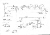
Thats a univibe right? At one of the other forums I frequent, a man by the name of John Hollis remade a more modern, simpler version that many people are very satisfied with. The schematic is at http://www.hollis.co.uk/john/circuits.html . It is called the easyvibe.
-Chris
Thats a univibe right? At one of the other forums I frequent, a man by the name of John Hollis remade a more modern, simpler version that many people are very satisfied with. The schematic is at http://www.hollis.co.uk/john/circuits.html . It is called the easyvibe.
-Chris
schematic
Looking back I think the others are right, they are electrolytics and not neons. As is pointed out, neons would have too large firing voltage for this equipment. The circuitry around these caps looks like a relaxation oscillator, where caps are charged until the transistors switch and then discharge the cap, then it all starts all over again. Haven't had time to look to that in detail though.
Jan Didden
Of course you will lose the vintage "tonality". Don't you know by now that nothing new is ever as good and the old thing it replaces. When things like color of wire insulation affect sound, it is a wonder than anyone bothers to build anything, because nothing is predictable or repeatable.
Of course it doesn't really matter if you lose the original vintage tonality. What matters is how you FEEL about it. If it makes you FEEL good, then it is OK.
MR
Of course it doesn't really matter if you lose the original vintage tonality. What matters is how you FEEL about it. If it makes you FEEL good, then it is OK.
MR
schematic
On a more technical level, one thing that will be different is the "attack" and "release" characteristics, because the characteristics of the lamp and VDR is different than that of the LED and VDR. You just will have to try and fiddle with the other circuit constants, depending how it sounds. But I understand that this is a proven design so it may be OK.
BTW, I would forget about the VDRs and use fets as variable resistances with the gates driven from the oscillator. But that means more fiddling and you may not want to do that.
Jan Didden
MRehorst said:CDS cells react to changes rather slowly compared to FETs. So do incandescent lamps compared to LEDs. That's where some of that "vintage tonality" comes from...
You could use thermisters glued to a resistor...
MR
You got a point there, Mark
Jan Didden
- Status
- This old topic is closed. If you want to reopen this topic, contact a moderator using the "Report Post" button.
- Home
- Design & Build
- Parts
- schematic questions