My young son has just been building a two transistor bistable (set/reset) flip-flop and the standard two transistor astable flip-flop (flasher) with a couple of LEDS in each. All as first steps into electronics.
His question now is how to make a bistable flip flop with only one switch as input that toggles on/off each time the switch is pressed. Obvious question but it has stumped me.
Years ago I did this by using two flip flops wired as a master and slave but this solution required many transistors and I'm not sure I could reproduce the thing anyway having hacked it on the fly at the time.
I have seen toggle flip flops built with two transistors, caps accross the base resistors and a parallel switch resistor connecting the emitters to ground (as here http://ourworld.compuserve.com/homepages/Bill_Bowden/page9.htm) Fine but I would prefer the input to go into some more normal place rather than brute forcing the negative rail up and down. Also we loose 1 volt from the suply.
So the challenge is, does any one have any nice discrete transistor toggle circuits that:
a) Use minimal components as my sons patients for building things is a bit short at the moment.
b) Uses a more "logical" input method.
c) Runs from a 5 to 6 volt supply, dictated by our rechargeable battery pack.
b) Can be easily understood by a 12 year old beginner. (Or me for that matter)
Extra caps and diodes allowed.
Cheers all.
")
Hello DIYAudio,
funny this thread should exist, as I am currently looking to build nearly the same component.
I unfortunately have no idea what to do with a .asc.txt file, but I did look at heater's circuit:
I have to say, wow, that's a lot of components.
Isn't there any easier (read, cheaper & smaller) way to build this circuit?
I don't really care if it uses transistors or relays, the important things are low cost, and hopefully also low power draw.
I found a circuit using three 4x relays, however those alone would cost about 21€, and seeing as I'm looking to build 5 flip-flops, 105€ is really too expensive for me.
Are there any cheaper ideas?
funny this thread should exist, as I am currently looking to build nearly the same component.
I unfortunately have no idea what to do with a .asc.txt file, but I did look at heater's circuit:
An externally hosted image should be here but it was not working when we last tested it.
I have to say, wow, that's a lot of components.
Isn't there any easier (read, cheaper & smaller) way to build this circuit?
I don't really care if it uses transistors or relays, the important things are low cost, and hopefully also low power draw.
I found a circuit using three 4x relays, however those alone would cost about 21€, and seeing as I'm looking to build 5 flip-flops, 105€ is really too expensive for me.
Are there any cheaper ideas?
If all you need is cheap, small and low power, just use two FF's in an IC -- 74hc74 or what was it again. Or even a 555.
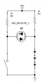
Concerning discrete, how about this one:
Bistable Multivibrators or Flip-flops
Concerning discrete, how about this one:
Bistable Multivibrators or Flip-flops
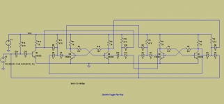
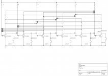
The circuits shown will not actually work as the OP wants: they require debouncing and fast, clean edges.powerbecker did it. It has 2 npn trans, 6 resistor, 2 cap, and 2 diode.
i removed the .txt extension into .asc, and opened it with ltspice.
Some more components would be required to make them work.
This circuit will actually work, and it is not more complicated.
As a bonus, one more based on a SCR:
Attachments
The circuits shown will not actually work as the OP wants: they require debouncing and fast, clean edges.
Some more components would be required to make them work.
This circuit will actually work, and it is not more complicated.
As a bonus, one more based on a SCR:
My young son has just been building a two transistor bistable (set/reset) flip-flop and the standard two transistor astable flip-flop (flasher) with a couple of LEDS in each. All as first steps into electronics.
His question now is how to make a bistable flip flop with only one switch as input that toggles on/off each time the switch is pressed. Obvious question but it has stumped me.
Years ago I did this by using two flip flops wired as a master and slave but this solution required many transistors and I'm not sure I could reproduce the thing anyway having hacked it on the fly at the time.
I have seen toggle flip flops built with two transistors, caps accross the base resistors and a parallel switch resistor connecting the emitters to ground (as here http://ourworld.compuserve.com/homepages/Bill_Bowden/page9.htm) Fine but I would prefer the input to go into some more normal place rather than brute forcing the negative rail up and down. Also we loose 1 volt from the suply.
So the challenge is, does any one have any nice discrete transistor toggle circuits that:
a) Use minimal components as my sons patients for building things is a bit short at the moment.
b) Uses a more "logical" input method.
c) Runs from a 5 to 6 volt supply, dictated by our rechargeable battery pack.
b) Can be easily understood by a 12 year old beginner. (Or me for that matter)
Extra caps and diodes allowed.
Cheers all.
Attachments
I recall that "Wave Generation and Shaping" by Strauss (amazon link) had a Tflop built out of two NPNs and a lot of discretes. Maybe I can find my copy somewhere.
What are you referring to that you recall Mark? Please post . The flip flop I posted I designed in the 90's.I recall that "Wave Generation and Shaping" by Strauss (amazon link) had a Tflop built out of two NPNs and a lot of discretes. Maybe I can find my copy somewhere.
Here is a link to the rest of the dtl switching I cropped that from.
https://hackaday.io/projects/hacker/1205951
I am referring to one of my textbooks from uni, written by Leonard Strauss -- (here is a review of the book). I have a memory that it contains a toggle flipflop made of a bunch of discretes and 2 transistors -- and we had to build it and demonstrate its operation in the lab. Maybe I can find my copy of that book, if so I will attempt to find that page, and if I do, post an image here. But don't hold your breath.
Wolf13 has stirred a 9 year old thread.
On a problem that I believe was well solved well before 1960. 1950s engineers were inclined to treat a good F-F plan as confidential because with bad Germanium a good plan could support million dollar computer contracts. But by 1960 G-E was exposing their thoughts in a book sold in all radio/TV repair distributors.
https://steampoweredradio.com/pdf/ge transistor manual/GE Transistor Manual Circa 1960 1.pdfhttps://worldradiohistory.com/BOOKSHELF-ARH/GE-Books/GE-Transistor-Manual-1964.pdf
Hello PBR
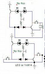
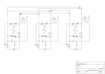
Your right they did do a good job . 60 years since a discrete component flip flop was released ? This one is a little different in some situations less parts are needed. The switching is done at the diodes. Very fast switching. Minimal parts. And expandable to multiple switch 3 way 6 way whatever you like.
Your right they did do a good job . 60 years since a discrete component flip flop was released ? This one is a little different in some situations less parts are needed. The switching is done at the diodes. Very fast switching. Minimal parts. And expandable to multiple switch 3 way 6 way whatever you like.
Last edited:
- Home
- Design & Build
- Parts
- Minimal toggle flip flop with discrete transistors required