Hey all,
Well I'm working on what will be my second PCB design. My first was a +-12VDC power supply that worked for a bit until I had a diode failure and haven't gotten around to fixing it yet.
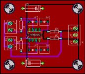
Anyway, this circuit is a basic 24db/oct highpass filter. This is my first try at a double sided PCB. I'm using Eagle and tried doing ground/power plains for the first time. Please let me know if I'm using them properly. Also, let me know if there's any big problems with the way I've routed things. I'm sure the more experience (maybe even lesser experienced) designers would be able to do a more simple layout.
Help is greatly appreciated. I'm going to send this design to a board house to have a dozen or so made for myself. I'm building a fairly complex active filter and I want to do it in modules.
Thanks!
-Scott
Well I'm working on what will be my second PCB design. My first was a +-12VDC power supply that worked for a bit until I had a diode failure and haven't gotten around to fixing it yet.
Anyway, this circuit is a basic 24db/oct highpass filter. This is my first try at a double sided PCB. I'm using Eagle and tried doing ground/power plains for the first time. Please let me know if I'm using them properly. Also, let me know if there's any big problems with the way I've routed things. I'm sure the more experience (maybe even lesser experienced) designers would be able to do a more simple layout.
Help is greatly appreciated. I'm going to send this design to a board house to have a dozen or so made for myself. I'm building a fairly complex active filter and I want to do it in modules.
Thanks!
-Scott
Attachments
I would like to suggest putting a couple more filter stages on the board, sharing power, and possibly using jumpers for signal lines between them. I anticipate that running all those power wires to screw terminals will result in complicated wiring, also the cost of screw terminals can add up.
- Status
- This old topic is closed. If you want to reopen this topic, contact a moderator using the "Report Post" button.