I intend to do a digital equalizer based on TAS3103 to put between my CD and my amplifier (which include a digital to analog converter).
I got samples and PC GUI (which seems to work fine: I have been able to generate coefficients).
As i work at Atmel, i plan to use an AVR starter kit between the PC and the equalizer board to parameter the registers (i plan to have an EEPROM on the board to store the parameters).
I plan to use only RCA input/Output.
TI evaluation board schematics are too complex, and i am looking for a simplier one with the minimum components to do the job.
Does anyone can help me ?
Thanks in advance.
Arnaud
click away ...
... this link: http://focus.ti.com/docs/prod/folders/print/tas3103.html
I like these app notes: http://focus.ti.com/lit/an/slea012/slea012.pdf

... this link: http://focus.ti.com/docs/prod/folders/print/tas3103.html
I like these app notes: http://focus.ti.com/lit/an/slea012/slea012.pdf

I ve got the GUY by someoneelse.
but the file is too big to be posted here.
Please send me an e-mail at the following adress:
arnaud.ruchon@free.fr
I will send you the files.
I am still looking for someone who would be able to design a PCB.
It looks too difficult for me.
Then i can help with samples of EEPROM, board to connect to the PC (I suggest ATMEL USBkey) and programmation of this board.
I also got 6 samples of TAS3103.
Arnaud
Hello Arnaud,
for the pcb-layout I'm the right.
I'm working as professional pcb-designer since twenty years, but ...
I have - always - special ideas!
So for prototyping, I design often small modules with only the
necessary parts on this module. So I can modify the construction
without stress.
The modules are plugged in connectors of a "Lochraster-Board".
(In this moment I don't remember the english word for this).
Later it's possible to design a complette board.
It's a really good idea to plan an USB-Interface.
So, for me this is not interesting to controll the Atmel
without PC. He should have only some predefined adjustment
for the TAS3103. It must be possible to do this without a
special USB-Controller
(refer to a remote interface for HometheaterPCs, but this program
is done in assembler)
Hello Kay,
My idea was to put an EEPROM on the TAS31003 board to store all parameters as described on TI schematics with jumpers between the EEPROM and TAS3103.
I propose to program the EEPROM trough the Atmel "USB key": http://www.atmel.com/dyn/products/t...=655&family_name=USB+Controllers&tool_id=3879
programmation would be quite simple:
It is easy to download a file in the microcontroller EEPROM with an existing Atmel PC software called "FLIP" and run a small firmware (that i have to develop) to transfer it to the EEPROM of the TAS3103 board.
Then the TAS3103 board could work in stand alone mode.
Is it ok for you ?
Arnaud
Hello Kay,
Correct, the board can work in stand alone.
The TAS3103 download the parameters from the EEPROM after start up.
I let you work on the PCB.
I will work on the firmware to download a file in the EEPROM and look again at the ALE GUY.
Fyi, in complement to what i explain at the beginning, my purpose is to compensate 1 way speakers based on Fostex FE168EZ.
According to people who have done such speakers, even without equalization, it is very very good so with a small comensation ... i expect to have something great.
In my case, for a simple implementation, input and output should be RCA.
What about you ?
Arnaud
Hello Arnaud,
>In my case, for a simple implementation,
>input and output should be RCA.
o.k., but this part of the AD/DA-Converters.
Once more, at this moment I plan only the necessary parts
on the pcb.
Most time, there is not all clear in the docomentations,
so it will be necessary to make changes. This will be
done better on a prototype, than the completed board.
And second, it must be possible to allow the people use
different converters, and so on.
The rest should placed on a board that holding the other
modules, like PowerSupply, Converters, Connectors and so
on.
You know, what I mean, for development, it's a good idea
to have a board with simple changeable modules.
Later, if all checked, we can decide, what is really
necessary to finish the project.
If you like to have a simple AD/DA-Converter-Board,
I have some for the TLC320ad77. I can send you without
costs. I have simple modules for the TAS3001 too.
All one-layer-boards, a guy checked this, and it works.
If you like to play with this, maybe for starting the
programming, give me a info.
But I send you only the boards, you must get the parts
from TI or others.
What's your reason for do that all and don't buy the
groundsound-board?
I need only a "intelligent subwoofer" with a delay and
three parametric EQs.
What AD/DA-Converters do you like to use at the end?
Do you have the knowledge to handle the soldering?
I post the new schema and the layout at
http://www.diyaudio.com/forums/showthread.php?threadid=88340
http://www.diyaudio.com/forums/showthread.php?threadid=88340
Hello,
Sorry for late feedback, i was quite busy those days.
Your approach with different small boards is fine for me.
The DIP module is great ! I need to further check your schematics but it looks OK (will try to do it today).
It should be OK to test the programmation.
Regarding AD/DA converter, i don't know which chip we should use. So, we can start with the one you already have as you have a board already validated.
With this board on top of the TAS3103, we should be able to do the first trials.
For the ferrite, i don't know either. The TI Eval board use a "Scientific conversions transformer 984-02": I had a look to the
Sientific conversion web site and couldn't find this device, it's may be obsolete. If so, we need to choose an alternative. Anyway, transformers seems to include already a ferrite. If you have any proposal.
Regarding soldering, i can manage, except may be the TAS3103 which have a very small pitch. I have only some manual equipments and my colleagues used to solder regularly told me that it would be very difficult to solder manually the TAS 3103.
You mentionned a Voltage limiter, TVS...., I can not finf it.
On which document / page is it ?
I have found no BOM on top of the EVM1 or 2 schematics.
I will check if we can convert the parameters from a analog filter to IIR or Biquad. I let you know.
You ask why i am doing all this ?
It is because i want to have digital equalizer to go with 1 way speaker project.
Do i answer your question ?
Best regards,
Arnaud
Hello Arnaud,
I hope some guys check my schema too, but I don't expect
any wonders.
I post it in another thread because I think, "digital"
may be better for the people to see it.
yes
I²C is 3V3 max.
For programming via Centronics-Port, we have to think
about reading from I²C, because I'm in doubt, that 3V3
is enough. May be the best way is level-converter.
But don't forget, a handling of the 'Reset' is not on the
module.
I hope some guys check my schema too, but I don't expect
any wonders.
I post it in another thread because I think, "digital"
may be better for the people to see it.
You ask why i am doing all this ?
It is because i want to have digital equalizer to go
with 1 way speaker project.
Do i answer your question ?
yes
we don't need it, if we can be sure, that the voltage onTVS...
I²C is 3V3 max.
For programming via Centronics-Port, we have to think
about reading from I²C, because I'm in doubt, that 3V3
is enough. May be the best way is level-converter.
But don't forget, a handling of the 'Reset' is not on the
module.
for test I use a resistor with 0RFB...
Hi!
The microcontroller i will use to program the EEPROM (or configure directly the TAS3103) is the ATMEL AT90USB128. It is a 3V device, so no issue with I2C voltage limit.
By the way, why do you mention programmation by centronics port ? What is it for ?
Best regards,
Arnaud
The microcontroller i will use to program the EEPROM (or configure directly the TAS3103) is the ATMEL AT90USB128. It is a 3V device, so no issue with I2C voltage limit.
By the way, why do you mention programmation by centronics port ? What is it for ?
Best regards,
Arnaud
Hello Arnaud,
maybe I or others guys can use I²C via Centronics.
o.k. and I forgot, that you use the Atmel-USB,
and so you don't need any protection on I²C!
why do you mention programmation by centronics
port ? What is it for ?
maybe I or others guys can use I²C via Centronics.
o.k. and I forgot, that you use the Atmel-USB,
and so you don't need any protection on I²C!
Hello Arnaud,
I become no negative feedback,
so, I can mail you the Gerber-files for production.
I send you the schematic. There I defined the corrections.
Please ask me, if you don't understand!
Should I send you the Gerber-Files for both?
Where do you like to produce the PCBs?
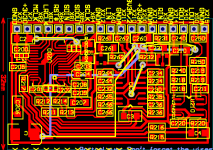
See the picture of the codec-board.
It's single layer too (50x32mm²), but with some wires
(blue).
Do you think we can go for the first assembly and trials?
I become no negative feedback,
so, I can mail you the Gerber-files for production.
For me is the TLC320AD77 enough.We can start with analog input/analog output.
I send you the schematic. There I defined the corrections.
Please ask me, if you don't understand!
Should I send you the Gerber-Files for both?
Where do you like to produce the PCBs?
See the picture of the codec-board.
It's single layer too (50x32mm²), but with some wires
(blue).
Attachments
Hi Kay,
haven't You been the one who rejected my offer for support for this project idea of Yours a couple of years ago? From what You used to reply back then, You wanted to finish this project quickly and not work together with people who take their time - and plan in months for their projects to come true...
...just for the record: You beat me by years!")
How is this project coming along?
Ciao,
Sebastian.
haven't You been the one who rejected my offer for support for this project idea of Yours a couple of years ago? From what You used to reply back then, You wanted to finish this project quickly and not work together with people who take their time - and plan in months for their projects to come true...
...just for the record: You beat me by years!
How is this project coming along?
Ciao,
Sebastian.
- Status
- This old topic is closed. If you want to reopen this topic, contact a moderator using the "Report Post" button.
- Home
- Design & Build
- Parts
- Digital equalizer - TAS3103