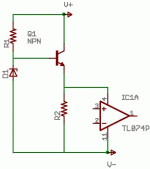
Hi,
It is possible , but gives only a single-supply version.Noise may be a problem as well.Regulators of this type are used sometimes.
There are many IC voltage regulators , like 7824/7924 , LM317 / LM317HV , and so on.
They should give better results , and short circuit protection as well.
It is possible , but gives only a single-supply version.Noise may be a problem as well.Regulators of this type are used sometimes.
There are many IC voltage regulators , like 7824/7924 , LM317 / LM317HV , and so on.
They should give better results , and short circuit protection as well.
Think more about failure modes: almost anything goes wrong there and you destroy the op-amp.
If you have a good idea of the max / min values of supply current, put a nice big fat resistance in series to drop most of the voltage, then the regulator.
Big resistors are almost bomb-proof.
If you have a good idea of the max / min values of supply current, put a nice big fat resistance in series to drop most of the voltage, then the regulator.
Big resistors are almost bomb-proof.
It's perfectly fine, and commonly used in commercially made equipment - as suggested, don't forget the decoupling capacitor on the supply to the opamp. There's no need for the minimum load resistor, the output won't float high even with no load.
As also suggested, if the transistor goes S/C you might get the full 60V on the opamp - but it's likely to go S/C to the base as well, and the zener has a chance of saving it - as long as it doesn't go O/C - it would be an idea to have a resistor in the collector of the transistor to limit the current in case of this. So move R2 to the collector instead, where it might do some good.
As also suggested, if the transistor goes S/C you might get the full 60V on the opamp - but it's likely to go S/C to the base as well, and the zener has a chance of saving it - as long as it doesn't go O/C - it would be an idea to have a resistor in the collector of the transistor to limit the current in case of this. So move R2 to the collector instead, where it might do some good.
davidsrsb said:60V is too high for most of the 3 terminal regulators.
A safer method is to use a 7824 with the transistor used as a preregulator.
Hi,
LM317HV seems to be a good choice , if available .
Regards,
Lukas.
Bazukaz said:
Hi,
LM317HV seems to be a good choice , if available .
I'd forgotten about the 317HV. I was trying to reduce parts count. I only need a single supply, so this would work from that standpoint. I guess 317HV would have about the same parts count. Now if only there were a fixed-voltage high-voltage regulator, e.g. if such a thing as a 7824HV existed.
Thanks for all the suggestions!!
--Greg
That would work, but keep this in mind when calculating R1 . Current thru the emmiter = base current + Collector current. What will happen is the current that will be drawn by the base of the transistor will be the collector current divided by Beta DC (HFE). The rest of the current going thru R1 will return to ground thru the zener diode. Zener diodes will only regulate voltage within a certian current range. You will have to look at the zener specs to find what that current is. When I use those series regulators I usually aproximate a value. Then use a trimpot instead of a resistor. One that is valued to give you a good USABLE range around the value of the resistor aproxamated.
example aproxamated R1 value of 600ohms use a 1k trimpot
or R1 value of 7.5k use a 10k trimpot.
If the zener has a broad current range using a resistor of aprox value will work. But I found that higher voltage zeners to be more fussy. But yours is somewhat of a low value so a resistor may be ok.
If that makes any sense.
- Status
- This old topic is closed. If you want to reopen this topic, contact a moderator using the "Report Post" button.
- Home
- Design & Build
- Parts
- Is this a legitimate way to power an opamp/comparator
