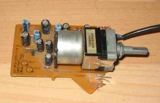
I managed to salvage this pot from a music centre system.
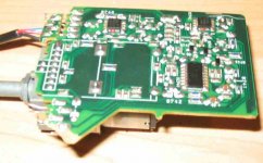
Problem is I dont know how to connect it as a manual pot - there are eight connectors going to the pot (seen on the underside of the board as the eight solder pads at the spidle end). There seems to also be two connections to the stepper motor (cylinder at back of pot)
I've searched but found no Alps pots with eight connectors - also tried to test with multimeter to check resistance of the connections with spindle rotation but so far no brekthrough.
Anybody know of or seen this part before?
John
jkeny said:What chances of getting the remote section of this working?
Hmm, depends. The pictures aren't really clear enough to tell what's what on the PCB. If you can trace what's in and out from the pot, then you'll know how many terminals you have left over. I'm guessing you'll have +5V, GND and an IR input (typically from a TSOP-style IR receiver/decoder) This is of course assuming the complete decoder for the remote signals are located on this board and not somewhere else in the device. If this is the case, a new receiver chip and a couple of passives should then be enough to get it working again.
jkeny said:Any idea how it is rated sonically?
John
I'd say slightly lower than the blue RK27, but it's still excellent for a chipamp or a small class D system for kitchen/office/bedroom use
")
/U.
Isn't that just a regular electric motor driving it? The brains of the system probably just fed it from an H-bridge to make it go one way or the other.
The easiest way to control it would be to use the guts of a toy remote controlled car. Forward makes the volume go up, reverse makes it go down.
The easiest way to control it would be to use the guts of a toy remote controlled car. Forward makes the volume go up, reverse makes it go down.
Hi,
I just took delivery of a different Alps version. Stuck the motor section on the current limited (100mA) output of my lab power supply, it started to turn at about 2Vdc and seemed fastish at 5Vdc. It turned both ways by just reversing the leads and used about 30mA (poor resolution of the current reading) rising to 40mA @5V.
I expect an H bridge would turn mine operating on about 5V to 6V across the transistors. I will use 317s to allow later adjustment down to 4 or 5Vdc if necessary.
The motor section has a slipping clutch so I do not plan any clever logic to remember where the pot is set. There are no outputs to monitor position anyway.
Mine had 22pins but the layout made it very easy to work out which went where.
- Status
- This old topic is closed. If you want to reopen this topic, contact a moderator using the "Report Post" button.
- Home
- Design & Build
- Parts
- Remote Control ALPS pot