Sorry to hear about your brother.
X7R has advantages as an HF decoupler in two ways: small so low inductance, lossy so damps any resonances. Its poor thermal stability and high voltage nonlinearity are irrelevant as a decoupler, but make it almost useless for many other purposes.
X7R has advantages as an HF decoupler in two ways: small so low inductance, lossy so damps any resonances. Its poor thermal stability and high voltage nonlinearity are irrelevant as a decoupler, but make it almost useless for many other purposes.
DF 96, of all people you are so like him. Thanks. His email address was Valvedabbler at AOL. com, I think that proves his interest. His understanding of semiconductors was unusual. He taught me how they work, only now do I start to understand. He taught me in 5 minutes what college failed to teach, it was Quantum mechanics made very easy as an aid to seeing the bigger picture. His great interest was TV beam tetrodes. Simon Pearson who sometimes is mentioned at the UK National Valve museum. DF 96 was one of his favourite devices, I have a box of them. He loved the PCL 86 and pointed out it was really a TV device which could be used for the audio output. His favourite TV's were ITT and Decca Bradford. He didn't like Sony, he said the colours were wrong and many other things.
Well being reminded of how much you learn from the influence of relatives has inspired me to try and teach my kids more...
Thanks.
I'm just beginning to try ceramics in places, am always looking to use the best part for the job, and most of my tinkering is around analog output circuits it seems, where I tend to jump to film parts. The low inductance is indeed a strong point.
Thanks.
I'm just beginning to try ceramics in places, am always looking to use the best part for the job, and most of my tinkering is around analog output circuits it seems, where I tend to jump to film parts. The low inductance is indeed a strong point.
Ditto from me Nige.Sorry to hear about your brother.
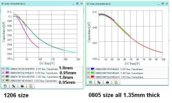
Temp and voltage variation of ceramic caps, or why your 4.7-uF part becomes 0.33 uFX7R has advantages as an HF decoupler in two ways: small so low inductance, lossy so damps any resonances. Its poor thermal stability and high voltage nonlinearity are irrelevant as a decoupler, but make it almost useless for many other purposes.
View attachment Temperature and Voltage Variation of Ceramic Capacitors.pdf
Dan.
Ditto also from me Nigel.
Dan the value of the decoupling capacitor is in a way irrelevant... there is a wealth of information regarding decoupling capacitors out there, having spent 30+ years messing with decoupling and power delivery systems for both digital and analogue circuitry I can tell you nthat on EVERY design I have worked on the decoupling capacitors have been X7R ceramic capacitors, with the odd COG/NP0 in places and on some designs X5R larger reservoir caps to get the size that will fit near the devices (when you are using 0201 decoupling caps the circuitry is pretty dense).
The critical factor for a local (next to the pins) decoupling capacitor is inductance and thus size of the package. If you look at the graphs for certain caps and their size once they go past the peak point in the graph they are essentially inductors and are of no use at higher frequencies.
DF96 says the use of class 2 ceramics (X7R,X5R) is limited to certain areas of the circuit where their tolerance is not going to have a detrimental effect on the circuit function, as also your links show as well... But this is what engineering a circuit is all about choosing the correct parts for a particular part of the circuitry, for domestic audio this is easier because of the limited operating temperatures, when you get into the -55/+125 temp range things become even more problematic.
There are a wide range of capacitor types available, for DIY where cost and space constraints are to an extent quite relaxed you can engineer a circuit and choose parts that are suitable for the job...
Further on high speed digital designs even the position of the vias connecting the caps to the relevant pins/planes can have a huge effect on the end result of the decoupling caps, get the via placement wrong and the cap inductance is so great that it becomes useless at the required operating frequency...
Last edited:
Thanks everyone. My brother worked at a specail needs school as their technician in Banbury Oxon . He also had skills as a builder and woodworker. His most remarkable skill was bonding with the special needs kids. So remarkable as he could live in the higher levels of science. No pensioner ever paid for TV repairs in his town if he was asked. One of his special things was a dartboard called Dartmaster. It worked by locating the dart by RF, the RF from a 4060. Dartmaster made under licence a replica dartboard using TV tube graphite paint to enhance the RF field ( marked with the trade mark of the owner the most famous UK make ). A ready made version wouldn't work. The point being it was exactly as a normal dartboard except the hidden electronics. The dartboard gave the score with big LED numbers. This was slightly daft as people pride themselves by doing the scores in their heads. None the less it did well.
Thanks for the SMD COG's
Thanks for the SMD COG's

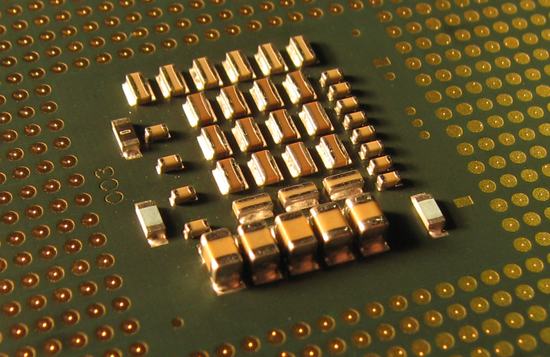
0612 vs 1206, remarkable difference in parasitic inductance.
Interesting. I always wondered why CPUs often have those short and wide ceramics.

As said inductance is the problem when decoupling, even then the caps are only good up to a few MHzs (20-30), the BEST option is planar capacitance created by using power/ground layer pairs with very thin dialectic between the plane pairs. Many of the newer BGA devices will also have some decoupling in built on the interposter PCB that forms the BGA device.
If you are doing Class D designs the 0612 type devices are a good design choice for both resistors and caps used as they minimise stray parasitic inductance on the layout leading to a better design. I have done a couple of layouts using these packages, not only do you decrease parasitic inductance ( a benefit in these high dI/dT circuits) but you also get improved thermal benefits for resistors as you have a lower thermal resistance due to the longer solder connections to the board relative to device area.
If you are doing Class D designs the 0612 type devices are a good design choice for both resistors and caps used as they minimise stray parasitic inductance on the layout leading to a better design. I have done a couple of layouts using these packages, not only do you decrease parasitic inductance ( a benefit in these high dI/dT circuits) but you also get improved thermal benefits for resistors as you have a lower thermal resistance due to the longer solder connections to the board relative to device area.
SMD do make sense. People get excited by " good " sounding resistors. I suspect these really do sound good. I often build Dead Bug circuits. This forces simple designs. Learning that COG 10 nF ceramic in 1206 exists means a Dead Bug RIAA is possible. MC33079 being not a bad frame.
Thanks for the kind words guys.
MMA02040C1501FB300 VISHAY, Surface Mount MELF Resistor, 1.5 kohm, 200 V, 250 mW, ± 1%, MMA 0204 Series, Metal Film | Farnell element14
Thanks for the kind words guys.
MMA02040C1501FB300 VISHAY, Surface Mount MELF Resistor, 1.5 kohm, 200 V, 250 mW, ± 1%, MMA 0204 Series, Metal Film | Farnell element14
I can see why you would say that. For Dead Bug they are worth a try. They pick up with a magnet. That is bound to make people avoid them. I hear no problems. Modern SMD solder well. For Dead Bud solder to a wire, then hold the wire to get it to the pin. The best sounding resistors I ever heard were Tyco foil types. A friend insisted I fit them ( PU loading ). They did seem better although measurements said nothing. At $20 a piece I won't be using them. He buys them in quantity for $8. All the same it's out of my league. The ones I listed seem close. To quantify it , the foil type seems less intrusive above 5 kHz. A lack of subtle popcorn noise perhaps. I was skeptical and remain so on price. It made me question if for logical reasons one type would be better. SMD was my thought and ears say yes. SMD GOG ceramic can be very good so I choose to think it a harmless preference to use my listed type of resistor. A bigger difference is to share the amplification using perhaps 3 paralell op amps. The noise is lower, more obvious is the noise is less blue. This is seen on the analyser also. It genuinely sounds different and nicer.
I should have said for commercial type production runs. MELF packaging for resistors and diodes was one of the first SMD packages, basically they are the PTH components without the leads... As I said they do crop up now and again but mainly in Mil designs where part approval is quite stringent and older type packaging and parts are often used as it is so time consuming getting newer components approved...
This is changing as automotive grade products are well specified, cover a wide temperature range and thus are easier to get approved for high reliability designs... worth looking at for components that may be in harsher areas or subject to temperature fluctuations, or where you just want to have a better specified component, used in domestic audio they are not going to be stressed to much temp wise but you do have a more reliable component...
This is changing as automotive grade products are well specified, cover a wide temperature range and thus are easier to get approved for high reliability designs... worth looking at for components that may be in harsher areas or subject to temperature fluctuations, or where you just want to have a better specified component, used in domestic audio they are not going to be stressed to much temp wise but you do have a more reliable component...
- Status
- This old topic is closed. If you want to reopen this topic, contact a moderator using the "Report Post" button.
- Home
- Design & Build
- Parts
- ceramic capacitors ?