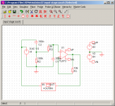
I am in the process of making my active crossover more robust with respect to noise, rf, grounding issues, and standards compliance. The new input buffer has a first order highpass at 10Hz, and a 160kHz first order lowpass. Tell me what you think.
I'm staying divergent from the diyAudio active crossover, I like mine better, and will make its pcb available after the redesign.
Also, anyone have any comments on using this ground isolation network for the active crossover?
http://www.adireaudio.com/Files/UcDPowerSupply.pdf
Thanks,
Lee
I'm staying divergent from the diyAudio active crossover, I like mine better, and will make its pcb available after the redesign.
Also, anyone have any comments on using this ground isolation network for the active crossover?
http://www.adireaudio.com/Files/UcDPowerSupply.pdf
Thanks,
Lee
Attachments
Hi,
your 10k on the inverting pin does not match the series 100k+5k on the non-inverting pin.
Why have you gone for purely passive single pole high pass?
Why 10Hz, it will have a roll off starting above 50Hz with the phase effects stretching even higher.
Is there any risk of shorting the output? Could there be any capacitance on the output? If yes, then add an output series resistor, between 10r and 200r.
Would there be any advantage in using a 47pF in parallel with the 10k feedback resistor?
As well as the polarised caps near the supply pins, hang 100nF off both supply pins to ground and consider adding a 47nF across the supply pins.
Thanks for the feedback, I obviously need to consult more resources. I'll maybe go see my science and engineering library today.
I decided using WinISD to put a first order rumble filter at 10 Hz, and by putting it in front of the whole crossover chain, the phase effects will be seen equally by all drivers. It seems bad to put this on the output using a capacitor, as the input impedence of the next device is not guaranteed.
I have been studying input and output stages of several devices, online examples, and kits I have, it is amazing how much the output at the top and bottom octave can be mangled. If you carefully study most amplifier specifications, many also have rumble filters possibly too high.
I don't think output will be shorted, do I need a resistive element between the output of a buffer, and the capacitance of a high pass filter?
I would like to avoid searching for good small capacitors, and have lived without them in my current version, I think I will leave that option open on the pcb.
I will be adding capacitance from the op amp pins to ground, I will read into your other noise reducing techniques.
Thanks,
Lee
Hi,
high pass active filter causes no problem to the TL072.
Capacitance to ground does cause it problems.
Aim for short connections between buffer and filter, no ground plane between the two, watch for other parasitic capacitance.
The filter stages are designed assuming zero source impedance, so you want to try without an output resistor on the buffer.
Or select a more tolerant opamp.
Ah, I'm sorry, I'm actually using the OPA2134 for now. I put that op amp into the circuit to run the simulation software.
No ground plane? I had bought linkwitz's boards which has one, and was designing my own to learn and customize it to my own application. What are the rules on using ground plane, are they just for digital circuitry?
No ground plane? I had bought linkwitz's boards which has one, and was designing my own to learn and customize it to my own application. What are the rules on using ground plane, are they just for digital circuitry?
Hi,
I didn't say
Ground planes seem to be popular in this forum. I reckon that some believe it raises the credibility of amateur designers, without understanding the pros and cons.
I have asked in two previous threads what a ground plane is meant to achieve at audio frequencies - silence! I really want to know because I recognise I am still leaning.
I didn't say
I saidNo ground plane?
You do not want parasitic capacitance around the input pins of the following opamp nor capacitive loading on the output of a susceptible opamp.buffer and filter, no ground plane between the two
Ground planes seem to be popular in this forum. I reckon that some believe it raises the credibility of amateur designers, without understanding the pros and cons.
I have asked in two previous threads what a ground plane is meant to achieve at audio frequencies - silence! I really want to know because I recognise I am still leaning.
Thanks for the quality replies, I think the ground plane issue might be something to do with the ExpressPCB documentation, which talks about it.
On the subject of feedback resistance, I thought it should be close to the 5k input resistance, and the 100kohm resistor from input to ground does not factor in. I looked at one book in the library and found some good input/output capacitance compensation formulas, but didn't find anything about the feedback resistor, I'll check the Op-amps for everyone guide again when I get the chance.
On the subject of feedback resistance, I thought it should be close to the 5k input resistance, and the 100kohm resistor from input to ground does not factor in. I looked at one book in the library and found some good input/output capacitance compensation formulas, but didn't find anything about the feedback resistor, I'll check the Op-amps for everyone guide again when I get the chance.
- Status
- This old topic is closed. If you want to reopen this topic, contact a moderator using the "Report Post" button.
- Home
- Design & Build
- Parts
- what do you think of my input buffer stage