I the past I have made layouts for double sided PCBs using resistor + transistor + diode pins to get the signal from one side to the other.
Caps are difficilt as they often hide the solderpads.
If you make the layout yourself just use the easiest way for you, or select parts that are easy to solder on both sides.
I have seen somewhere that you can get a small metal tube to insert in the PCB hole, this will make a "plated" hole that allows for pad hiding parts to be soldered. It may need bigger pads than normal, but if you do the layout yourself you should have no problem with it.
\Jens
clem_o said:In that case, make sure any feedthrough connections do not occur on a component leg.
Cheers
For what reason?? This has been done for ages, and is still done in prototyping where you don't have plated holes...
I sometimes use the small rivets Jens is referring to, they are good, but finicky and time consuming ( and expensive tooling) - I only use them if I have to, like on high density boards an on RF groundplanes.
Component legs are easy and no extra cost.
You can also use some very thin wire - like 32 g wire wrap- if there is room for both, but it sometimes require some tricky soldering....
AuroraB said:
For what reason?? This has been done for ages, and is still done in prototyping where you don't have plated holes...
For the reason that the originator of the thread felt it was 'awkward' to do so.
The other reason - it avoids heating the component at a point very near the die, which can cause failure if temp is too high / interval too long for soldering. Of course, its all very dependent on how skilled the person is; I am sure that many people feel fairly confident to go ahead and solder at that point, but persons without that much experience may feel more comfortable avoiding such a situation...
Cheers!
I've been hand soldering for almost 40 years now, and I truly fail to see how it can be awkward to solder both sides of a resistor, transistor etc. The problems of course arise with things like radial ellytics and other parts that cover the top pad- in which case other means have to be used- like feed-troughs outside these component areas.
The heat is a minor problem - assuming one has aquired basic soldering skills and good tools - a normal solder joint should take no more than 2-3 secs to complete. It is also common practice in prototyping these days to hand solder SMD's, SO's, QSOP and a lot even worse....
It does require a steady hand and lots of patience..don't rush it...
If you don't feel you master the "art of soldering" - please collect some info and practice before you waste your money on expensive parts..
Anyone here old enough to remember the first MOSFETS from the early 70ies??? You'd be lucky if one of 3 survived soldering at all.......until you learned the tricks.....
End of discussion from my end
Tup an bottom soldering isn't too hard. If there are tall compuntes near by, it can make the point you are trying to solder difficult to reach. Mostly you just need to think things out when you layout the PCB.
Also DIP-8 & 14 packages are tricky to top solder without making solder bridges. The easiest pins to use for connecting to a topr trace are the ones on the four corners.
What can be trickier is "registration", getting the pads in the same place top and bottom. Using larger than normal pad where possible gives you some latitude. I use a phot-etcg systen and make the two patters on transparency film taped together to form a packet. Then slip in a double sided unexposed PCB, sandwitch the whole thing between two sheets of glass. Then expose obe side, flip it over and expose the other.
Final note-- after laying out a 2-sided board, I take a second look an see how many top traces could be eliminated by a bit or re-routing. About half the time I find that I can reduce the number to the point that the remaining traces can be replaced by buss or jumper wires. Then I'm back to single sided again.
the first MOSFETS from the early 70ies...........?
My daddy showed me how to make and use a cats whisker crystal radio(a real crystal, not those diode thinggies) when I was just a puppy.
Soldering was done using canned flux and a pot of molten solder you dipped the heated iron into. Tinning both pieces first was of course imperative and commonly understood good practice. Ah..... the old days before electricity.
An Account of the Kite Experiment
From Carl Van Doren's "Benjamin Franklin," ©1938 by Carl Van Doren
The episode of the kite, so firm and fixed in legend, turns out to be dim and mystifying in fact. Franklin himself never wrote the story of the most dramatic of his experiments. All that is known about what he did on that famous day, of no known date, comes from Joseph Priestley's account, published fifteen years afterwards but read in manuscript by Franklin, who must have given Priestley the precise, familiar details.
This happened in June 1752, a month after the electricians in France had verified the same theory, but before he heard of anything they had done."
Franklin's work became the basis for the single fluid theory. When something is being charged, such as a car battery, electricity flows from a positive body, that with an excess charge, to a negative body, that with negative charge. Indeed, a car battery has plus and minus signs on its terminals.
Franklin wrote Collinson in another letter that: "I feel a Want of Terms here and doubt much whether I shall be able to make this intelligible." Not only did Franklin have to posit theories, he also had to create a new language to fit them. Some of the electrical terms which Franklin coined during his experiments include:
* battery
* charge
* condensor
* conductor
* plus
* minus
* positively
* negatively
* armature
They are still the terms we use today.
Benjamin Franklin was the most famous American in his day. Wherever he went, crowds formed. People worldwide pictured Franklin when anyone said, "American."
The remarkable Benjamin Franklin, a printer by trade, a scientist by fame, and a man of action by all accounts, continues to shape American thinking and action. The Independence Hall Association, owners of ushistory.org, has commissioned and assembled resources for you to explore the diversity that was Benjamin Franklin.
Well.. we could start a discussion of which side of the pond has played the most important part in the history of electricity, but honestly I think we should defer.. I think the real balance is fairly evenly distributed.....
On the subject of PCBs I totally agree with PinkMouse- it is just a matter of mental awareness to what you are doing.
If you plan to have boards factory made, you more or less automatically assume plated through holes, although doing without might save a few quid.
I have been making my own boards since I was a BSc student in the early seventies, and double sided has been common practice in RF for even longer, constantly using the legs for component side grounding and feed through, upper side mainly being used as ground plane and limited routing.
My technique for makking double sided boards, is to make the films into an envelope, and stick the board inside. If you have to flip the board for single sided lighting, the board should be oversized, so that the envelope can be taped to the board itself.
Using diagonally placed index holes, drilled after the first side is done, is another method
My comment on the early MOSFETs was mainly related to RF types, which was so static sensitive they would poof just by looking at them!
Cat whisker crystals?? Aree yo talking to me???
I'm not that old!!!!! ( But I was a very young engineer when I started a professional life )
homebrew duel sided pcb for lm4780
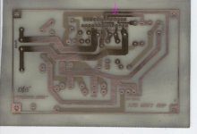
just made this one from national semi data sheet info it is a bridge config for the lm4780 . toner one side drill a couple of holes and line up the other side to the drilled holes makes sure to use fine sand paper on the drilled holes so there are no burrs. toner the other side touch up any bare copper around the holes with a marker and etch. the arrow is where a trace will be connected via a piece of wire.
just made this one from national semi data sheet info it is a bridge config for the lm4780 . toner one side drill a couple of holes and line up the other side to the drilled holes makes sure to use fine sand paper on the drilled holes so there are no burrs. toner the other side touch up any bare copper around the holes with a marker and etch. the arrow is where a trace will be connected via a piece of wire.
Attachments
"Cat whisker crystals? I'm not that old!"
Some of us are.
Got boots older than your soldering career. Being old don't make one smart, we just made more mistakes to learn from. Fortunate to come from a line of people who knew: make things, make do or do without.
Using computer software to create a layout is a great tool. Hand drawing it on acetate teaches a different lesson.
Even in his time, Ben was considered a flirt, rake and womanizer. But was also a gentleman who didn't brag or tell. Seems none of the ladies did either. He sired a son out of wedlock before his marriage to
Deborah Read. History does not record the woman's name.
Ben became a rebel after the "intolerable tax" imposed by the King.
- Status
- This old topic is closed. If you want to reopen this topic, contact a moderator using the "Report Post" button.
- Home
- Design & Build
- Parts
- homemade double-sided PCB