I'm building an integrated gainclone (audiosector) with the 2 toroids in fairly close proximity to the signal circuitry (small enclosure), and would like to minimize EMI within the chassis. How best would I accomplish that?
Can I use a grounded steel or aluminum divider between the power supply and the audio circuits? Does this help with EMI as it does with RFI?
Also, can I use a grounded metal conduit to provide a shielded path for the input lines from rear connectors, between the two toroids, to the audio circuits at the front?
..Todd
It may help to examine shielded transformers. The thing is, they use iron shells. As aluminium is non magnetic, you'll only get rfi shielding with them.
As far as I understand it, the magnetic field will blend into the shielding, but the effect is not complete. You may want multiple layers.
For this reason, I choose physical separation, and find experimenting with orientation will help.
Unfortunately, I think the channel idea will be less than satisfactory.
I believe you're right (about ferrous/aluminum), based on what little I know. Thanks for responding, Indm.
Distance is a luxury I have decided to forego based on the chassis I have available, so I will have to live with the close proximity of the two 300VA 22+22v toroidal power transformers. I'm just trying to determine how best to minimize the deleterious effects.
So, how about this... What if I can find a steel dish/bowl/saucepan that would fit nicely over the toroidal transformers. Is there anything special I would need to do to them? eg: Grounding techniques, or avoiding an inadvertent shorted winding. I haven't seen a shielded toroid up close before, so I'm not sure what's involved.
Surely applying some of these shielding techniques will be helpful to some degree right? I wish I knew more about it.
..Todd
Yes, I agree it will help.
I think your concerns will be hum, and feedback through the power supply. I think concentrating on the hum will bring you to a good result.
Conventional xfmr shields are just like a lamination that bumps over the windings. Sorry, I can't be certain about not creating a shorted turn, but it seems worth a try if there is a little air space inside the shield.
It is common to ground a xfmr body. I would ground the shield.
You can reduce radiation by ensuring current spikes are kept to a minimum. This can be done by not using massive electros, or by adding series resistance before the caps. You might also put snubbers on your diodes.
Hi,
producing an effective EMI shield from a metal case is difficult.
Every hole in the case becomes and exit/entry point for EMI transfer. The solution to be placed around every hole is quite complex.
Similarly every cable through the enclosure becomes an aerial.
Some time ago Marantz and others introduced copper plating to steel cases. Was this an attempt to stop both electric and magnetic fields?
Good move using toroids in this application, they obviously minimise leakage fields.Once the amp is built, loosen the toriod mountings and rotate the transformers slowly, listening for minimum hum - there is usually a minimum to be found (it's to do with the where the leads leave the windings).
Other than that, keep all AC wiring (including anything to/from rectifiers) tightly bundled or twisted together to minimise loop area. Good luck!
Other than that, keep all AC wiring (including anything to/from rectifiers) tightly bundled or twisted together to minimise loop area. Good luck!
Many good points...
Toroids are inherently quiet (magnetically)... a good choice for close work. Martin Clark is right on the money with orientation.
Another good trick is not to make noise in the first place. Hum probably won't be your problem... but radiation from rectifier diodes could be... snubbing the rectifiers would be a good idea here. There are a few good threads on this.
Think less about wrapping the transformer in a can. Think more about a wall between your entire PSU and your amps.
And yes, a picture is worth a thousand words...
I will certainly allow for rotating the toroids after everything is assembled. Thanks.
It's fairly simple to put a steel baricade shield between the PSU and the amp circuits. Currently the heatsink (aluminum) sits between the 2 sections.
As for the rectifier diodes, Peter Daniel's circuit uses a total of 16 MUR860 diodes (a bridge per rail @ stereo), I can add snubbers to Peter's low capacitance supply, but I recall him mentioning that to use snubbers, I'd have to revert to using big electros. (Which isn't really a problem either).
In his design, the amp boards have a pair of 1500uF caps. Then a small 10uF cap exists on the rectifier board. I don't understand how this low-cap supply works. I do understand using a big honkin bank of 10kuF caps, and I have a pile of them kicking around if needed.
PSU: http://www.audiosector.com/lm4780 psu.pdf
AMP: http://www.audiosector.com/lm4780 amp.pdf
I'll take a photo of my set-up when I get home this evening.
..Todd
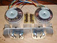
Well, you'll have to rely on "theatre of the mind" to view the chassis, which is currently undergoing an Akai-mod-ectomy.
What you see will fit nicely in the 12" x 12" (30 cm) x 3" (76mm) chassis. This photo is probably a rear view. But if I use an attenuator of some sort I might have a problem getting its shaft through the heatsink and up to the front.
..Todd
What you see will fit nicely in the 12" x 12" (30 cm) x 3" (76mm) chassis. This photo is probably a rear view. But if I use an attenuator of some sort I might have a problem getting its shaft through the heatsink and up to the front.
..Todd
Attachments
- Status
- This old topic is closed. If you want to reopen this topic, contact a moderator using the "Report Post" button.
- Home
- Design & Build
- Parts
- EMI shielding... how?