To cut a long story short I've determined that power is going into the pcb of my Marantz amp.
It also comes out again to serve the remotely controlled volume control.
Use to be when I switched on there would be a powering up thump. That doesn't happen. Could it be related to the relay?
There is a relay VB-24MBU-510
Does that mean anything to anyone?
Can a relay fail?
Thanks Alan
It also comes out again to serve the remotely controlled volume control.
Use to be when I switched on there would be a powering up thump. That doesn't happen. Could it be related to the relay?
There is a relay VB-24MBU-510
Does that mean anything to anyone?
Can a relay fail?
Thanks Alan
Not entirely sure
Well..when the case was on in normal use there was definitely a powering on thump which may have been in tandem with a click. I'm pretty sure there was a click but not %100.
I'm just wondering if the relay failed, (and can they?), would that stop the output to the speaker terminals and also the headphones and is there any way of testing it?
Regards
Alan
Hi Alan,
That tells me that the unit is in protection mode.
If you look on the board near the heatsinks you will see some 0.18 ohm dual resistors. They look like skinny white boxes with three legs. Measure the DC voltage at the centre leg. Don't leave the power on longer than you need to. The meter should read close to zero, less than 20 mV with that circuit I'd guess. Measure both channels.
I'll respond in the thread rather than via PM. I see you got poobah's attention already.
-Chris
 anatech,
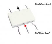
Hi Alan,
Good. Those measurements make sense.
Now, if you feel you can, measure between the center of the resistors and each base in the stage, outputs and drivers. Be careful your probe does not slip 'cause the centre lead is the collector.
Write the measurements down. Call out the readings and someone else write.
-Chris
Hi Alan,
Some assistance from a more experienced person may help here. I don't want an accident to cause much damage. That would be a person right at your side to guide you.
My intention was for you to give me the base voltages of the drivers and outputs with respect to the common point of the emitter resistors.
-Chris
- Status
- This old topic is closed. If you want to reopen this topic, contact a moderator using the "Report Post" button.
- Home
- Design & Build
- Parts
- Relays in amp