I got a brand new fire wire sound card that I could use for measurement on my power book and PC laptop. I also have some measurement software as well as pc oscilloscope. My problem is that some of the software requires to send signal from the output of the amp to the sound card input. That calls for some kind of attenuation. I made jig that allows me to use osciloscope probes but I am not sure that x10 attenuator in the probe will work, and even if it works sometimes that is not enough.
Is there any suggestion how to construct some kind of voltage devider - attenuator that will work well, and maybe some overvoltage and spike protector. I am assuming that kind of circuit should have very high impedance in order not to interfere with measurement circuit - just like oscilloscope. I am not sure if regular voltage devider is OK, where I could use - let say 1 Mohm resistors. Is there any problem connecting that in the amp output in parallel with dummy load?
Thank you, this will be a great help
AR2
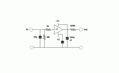
If you are using the card to measure the output from a power amp, you don't need high impedence in the attenuator. It should be on the order of 1/10 the input impedence of your sound card. Easiest is to use a pot in parallel with your amp load, wiper attached to amp output. You can, of course make a simple resistive divider, which is safer because you can't forget to set it properly. Or, for protection you could use antiparallel zener diodes across the output, with a voltage rating equal to or less than the safe input for the card.
Sheldon
Sheldon
Thank you for the detailed explanation. I am planning to use this jig for amp measurement as well as for PC osclloscope measurement. Is it possible to use osciloscope probes and if it is why doesn't x10 attenuation doesn't work?Could you suggest set up for that as well. When you say antiparalel zeners - does it mean two zeners back to back?
A 10x scope probe will work as long as you connect it to a buffer with a 1Mohm input impedance and whatever shunt capacitance that the scope input has. For example, the 10x probe I use connects to a 1M/20pF across the input of a BUF03. The reason I use the 20pF is that my scope has a 1M/20pF input, and that's what the probe is designed to see. The probe should have its compensation adjusted, which you can do with the scope calibrator and looking at the buffer output with your 1x probe.
AR2 said:Thank you for the detailed explanation. I am planning to use this jig for amp measurement as well as for PC osclloscope measurement. Is it possible to use osciloscope probes and if it is why doesn't x10 attenuation doesn't work?Could you suggest set up for that as well. When you say antiparalel zeners - does it mean two zeners back to back?
I don't know about PC oscilloscope, but SY won't steer you wrong. On the zeners, actually I had a brain cramp. You would not connect them in parallel, but in series (back to back or front to front) as you suggest, in opposing polarity. That way, output peaks will be limited to the zener voltage rating (plus about 0.6v). I guess that you could use a series of regular diodes connected anti-parallel (in parallel but again in opposing polarity). In this case, three each direction would give about 1.8v before conducting. Or maybe even a series of anti-parallel LED's (SY?). If you get a light show your output is too high.
Sheldon
")
- Status
- This old topic is closed. If you want to reopen this topic, contact a moderator using the "Report Post" button.
- Home
- Design & Build
- Parts
- Attenuator for sound card measurement