Hi,
I have read numerous safety notes about "if you unsure about making a power supply, then don't!" But I figured that there is a first time for everything. Anyway, I have all the bits together. My 500VA transformer is rated as follows:
Prim: 2x115V Brown/White - Black/Pink
Sec: 2x40V Red/Yellow - Blue/Grey
* Because I'm in the UK (240V from the mains), I soldered the White and black together.
* I wanted +-55V so I soldered Yellow and Blue together to be ground.
* I soldered the Brown and Pink to the mains socket, via a 4A fuse and a switch
* I soldered the Red and Grey to the AC sides of the 35A rectifier.
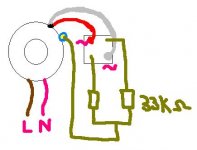
* I didn't have enough solder for the caps, so I soldered two 33k resistors to the + and - of the rectifier to the Yellow/Blue
* Nothing is touching the chassis.
When I turned it on, there was nothing! I was expecting 57V (ish) AC from the rectifier, but the fuse had blown! This happens repeatedly!
Any ideas?! I have included a picture to confuse you even more!
Thanks
Gaz
I have read numerous safety notes about "if you unsure about making a power supply, then don't!" But I figured that there is a first time for everything. Anyway, I have all the bits together. My 500VA transformer is rated as follows:
Prim: 2x115V Brown/White - Black/Pink
Sec: 2x40V Red/Yellow - Blue/Grey
* Because I'm in the UK (240V from the mains), I soldered the White and black together.
* I wanted +-55V so I soldered Yellow and Blue together to be ground.
* I soldered the Brown and Pink to the mains socket, via a 4A fuse and a switch
* I soldered the Red and Grey to the AC sides of the 35A rectifier.
* I didn't have enough solder for the caps, so I soldered two 33k resistors to the + and - of the rectifier to the Yellow/Blue
* Nothing is touching the chassis.
When I turned it on, there was nothing! I was expecting 57V (ish) AC from the rectifier, but the fuse had blown! This happens repeatedly!
Any ideas?! I have included a picture to confuse you even more!
Thanks
Gaz
Attachments
C
CryingDragon
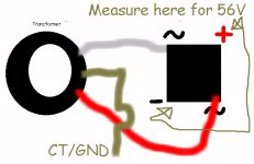
try taking the center tap off you you have 3: your CT your + and - and test from the + and - to eachother and from them to the CT you should get yes about 56V from - to + and your rated voltage from each one to the CT. It seems like your shorting the secondary (you don't need those resistors).
Banned
Joined 2002
Banned
Joined 2002
Banned
Joined 2002
Hi,
OK, thanks for the great response!
* Nothing is touching the chassis nor Earth. Just Live and Neutral.
* The fuse was rated at 250V 4A. Ceramic type.
* All testing must stop until tomorrow when I get new fuses!
* The reason I put the resistors there was so that it would pull a current, albeit under 50mA. I thought power supplies overloaded without a load.
* I did try without the resistors first, but the same thing happened.
It is a brand new xformer and I'm sure that it all connected the right way around.
Gaz
Banned
Joined 2002
Hi.
I have the amp here on my lap (it has bass isolation spikes from a loud speaker attached to the bottom, so with the weight of the heatsinks and xformer, it is quite painful!)
I have taken off the resistors, and will get some fuses tomorrow.
The wiring is correct according to your suggestions. The only thing I can think of is that it is dependant on the polarity of the mains in...but it is AC, it shouldn't matter!
There are no short circuits...
I can't even take pictures for u to look at until the 8th Nov when I give my GF a digital camera for her bday!
Gaz
Hi,
No, I didn't use anything like that. I dont really know anything about them or the point of them. I am using a ceramic slow blow fuse though. Is that the same / adequate?
Just checked ESP website....I did notice the lights dim briefly but no humming or any audiable noise.
Thanks,
Gaz
No, I didn't use anything like that. I dont really know anything about them or the point of them.
I am using a ceramic slow blow fuse though. Is that the same / adequate?Just checked ESP website....I did notice the lights dim briefly but no humming or any audiable noise.
Thanks,
Gaz
IT does matter how you wire primary and secondaries . There should be a little marking or dot telling you which end is the starting point.
1. ------
*) |
) |
) |
2. ------ |
3. ------ |
*) |
) |
) |
4.-------
You would connect 2 and 3 together, and use 1 and 2 for input. If you wire it for 120volts, then 1 goes to 3, 2 goes to 4.
Same goes for secondaries.
1. ------
*) |
) |
) |
2. ------ |
3. ------ |
*) |
) |
) |
4.-------
You would connect 2 and 3 together, and use 1 and 2 for input. If you wire it for 120volts, then 1 goes to 3, 2 goes to 4.
Same goes for secondaries.
Your suspicon is correct. It does not matter which is Live or Neutral.
I suggest that you completely unsolder the secondaries and see if the fuse blows. As far as I know an unloaded transformer is quite content sitting by itself. Then you can check the voltages. If this fails, send it back, for it is broken.
Good luck,
Dan
I suggest that you completely unsolder the secondaries and see if the fuse blows. As far as I know an unloaded transformer is quite content sitting by itself. Then you can check the voltages. If this fails, send it back, for it is broken.
Good luck,
Dan
Gaz;
Tough to troubleshoot from around the world but;
I don't think that it is normal inrush that is blowing the fuses.
It is possible, but unless you are using high speed fuses,
I doubt it.
So lets assume you've got it wired wrong. I'll try to explain
what I did wiring my transformer. This could take a while...
I have a dual primary 750 VA transformer, and I didn't know
the lead color codes, so I had to experiment. I applied 120
to two leads randomly and watched the secondary voltage.
When I saw voltage on the secondary, I knew I had one primary
winding connected properly.
OK, so now I need to hook up both primary windings to 120.
Take a look at the schematic posted by Jean above. If I put
the hot on 1 and 3, and the cold on 2 and 4, life was good.
But if I put the hot on 1 and 4, and the cold on 2 and 3, the
fuse blew.
Moral of the story: If your primary windings are connected
in opposition, they cancel and flux in the core is zero. No back
EMF means your windings look just like low impedance wire
to the source, and they will blow fuses.
This is really just a long way to say disconnect everything from
your secondary and plug it in. If the fuses still blow, check
your primary...
-herm
Hi Rarkov,
It sounds like you have an old ILP transformer, they are the only ones I know that use that combination of colours!
On the output side, you should connect yellow and blue together and use them as your earth, and the grey and red should go to your rectifier,(red/ yellow is a pair, and blue/grey is a pair).
This should give you then your plus and minus and earth, ready for smoothing.
On the input side, ILP used various schemes, ( but mostly using black/white as the 240v markings and joining the pinks), so your best bet is to use the technique described by herm to find the particular way your trannie is wired.
Good luck, and stay safe
- Status
- This old topic is closed. If you want to reopen this topic, contact a moderator using the "Report Post" button.
- Home
- Design & Build
- Parts
- Why does my PSU KEEP blowing fuses?!