The axe is for calibrating the backyard trees. The 4.5-digit Fluke meter bracketed to the bottom of the bench is for calibrating electronics! ")
The flying leads were dragging into other stuff (predictably). This made a short circuit between two important things. The small supplies shut down due to over current. I got frustrated and hooked up the big supply shown... *pop* from the amplifiers...
scratch one more stinky TL074ACN package.


I was getting to the very dark part of the tunnel with these amplifiers... I was starting to toy with the idea of actually SPENDING the first dollar on this project : :. Then I got one to work right. YAY!
Does anyone else ever fiddle with levels just to watch readouts go up and down?
The flying leads were dragging into other stuff (predictably). This made a short circuit between two important things. The small supplies shut down due to over current. I got frustrated and hooked up the big supply shown... *pop* from the amplifiers...
scratch one more stinky TL074ACN package.
I was getting to the very dark part of the tunnel with these amplifiers... I was starting to toy with the idea of actually SPENDING the first dollar on this project :
:. Then I got one to work right. YAY! Does anyone else ever fiddle with levels just to watch readouts go up and down?
w.o.r.k.i.n.g
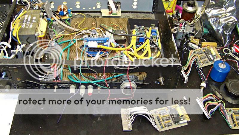
all 3 instrumentation amplifiers are working and rough-calibrated. Mind the polarity on the inputs! Mounting the amps was a head-scratcher but it's done. They are wired in as are the meters. One of the meters came up missing a digit (again) DOH! A little solder and it's back. I haven't done the switch for PNP devices or done any functional tests (rule: don't try to make it work the same day you worked on it) but I *should* now have a basically functional NPN transistor tester.
finally...
all 3 instrumentation amplifiers are working and rough-calibrated. Mind the polarity on the inputs! Mounting the amps was a head-scratcher but it's done. They are wired in as are the meters. One of the meters came up missing a digit (again) DOH! A little solder and it's back. I haven't done the switch for PNP devices or done any functional tests (rule: don't try to make it work the same day you worked on it) but I *should* now have a basically functional NPN transistor tester.
finally...This project is still on the front burner, but life is in the way
I was using the new low voltage power supply and suddenly it stopped working after a short period of failure.... I am rebuilding it since this is the best way I have of injecting a known low voltage. I think the thing that killed Rev. A is the 20+ volts on the base of a 2N6037. oops. So I am completely redoing it. I rewound the secondary of another transformer for low voltage, got a nice power filter out of a server power supply, along with something like 0.25F for filtration and a deeep reservoir. 2N6037 upgraded to TIP102. Looks the same outside, more better inside. It's about 1/2 done now.
I was using the new low voltage power supply and suddenly it stopped working after a short period of failure.... I am rebuilding it since this is the best way I have of injecting a known low voltage. I think the thing that killed Rev. A is the 20+ volts on the base of a 2N6037. oops. So I am completely redoing it. I rewound the secondary of another transformer for low voltage, got a nice power filter out of a server power supply, along with something like 0.25F for filtration and a deeep reservoir. 2N6037 upgraded to TIP102. Looks the same outside, more better inside. It's about 1/2 done now.
I was fighting myself on that power supply... the compaq server power supply filter had a resistor (thermistor?) inline that was severely limiting current at 3VAC. Bypassed that after doing some big-time upgrading to the rest of the circuit for troubleshooting. The transformer is now wound for about 5VDC off the rectifier to give the transistors some breathing room. Transistors are a 2n6045 driving 8x 2n4918 in parallel. The limiting factor I think is going to be the transformer now...
Anyways I got the power supply to supply current... 1.8A @1.8VDC, 6A @ 0.6VDC (1 & 0.1 ohm resistor loads)... enough for testing LEDs and gigohm-input amplifiers anyway, so call it done. Now I'm back to the transistor tester. Finally.
And all this would have been done already but I had to make some room for my new compressor in the shop!
...that compressor, it works great BTW
The circuitry for a thermally-controlled test bed is done. Control is within a couple of degrees +/-. Minco heaters are very handy for this application... 30VDC/3A max draw... Time for another power supply! (d'oh!)
Minor work progresses on the tester itself... life gets in the way.
The circuitry for a thermally-controlled test bed is done. Control is within a couple of degrees +/-. Minco heaters are very handy for this application... 30VDC/3A max draw... Time for another power supply! (d'oh!)
Minor work progresses on the tester itself... life gets in the way.
The intra-chassis grounding with which I was so pleased, I have to undo. It would have been great if I were going for an NPN only tester. With P-channel devices the entire test circuit has to be floating so I can flip power polarity.
Yeah, so I didn't quite realize that when I flipped poliarity the first time... (crack crack, smoke)


 The bridge rectifier for the DUT power supply bit the big one. Fortunately without actually exploding but still.
Just about decided to scrap the whole project. Then I decided to go ahead instead of wasting all the time/materiel that have gone into the projcet.
Need to come up with a power supply tho... It would be handy for the heaters and instrumentation amplifiers to share the same 30V. The 5v for the meters would be spiffy, if it could come off the same transformer... we'll see how I do it. It has to be done because the switching bricks have non-isolated grounds...
edit: oh, still sitting at $0.00 for the project, not counting time.
Yeah, so I didn't quite realize that when I flipped poliarity the first time... (crack crack, smoke)
The bridge rectifier for the DUT power supply bit the big one. Fortunately without actually exploding but still.Just about decided to scrap the whole project. Then I decided to go ahead instead of wasting all the time/materiel that have gone into the projcet.
Need to come up with a power supply tho...
It would be handy for the heaters and instrumentation amplifiers to share the same 30V. The 5v for the meters would be spiffy, if it could come off the same transformer... we'll see how I do it. It has to be done because the switching bricks have non-isolated grounds...edit: oh, still sitting at $0.00 for the project, not counting time.
Back From The Grave . . . Again!
 You all had forgotten, but I've been looking at this thing on my bench every time I go out to the shop. Two more children, a cylinder head porting job, and life in general have conspired to show me just how far back the "back burner" really is.
The transistor tester is now back to the front burner (for now) (again).
After completely scrapping and redesigning the thermostatically-controlled test bed, that is now working. The temperature is adjustable and very well-controlled. That is going to be its own thread sometime in the next (mumble) days. The low voltage precision power supply is going to get its own thread as well, and it too has been revived after (count 'em) two more show-stopping failures.
The heat sink for the heated DUT test bed has put me right over the size limit for my 4" high chassis for this project. I need a new chassis, preferably at least 4U high. I may be able to swing it free from work, so after 6+ years (on and off) and at least two complete re-dos on this project I will still be out a total of $0 for components. We just won't talk about man-hours spent . . .
With each new chassis comes a major circuit revision, so here I go again.
I'll be keeping some of the power supply bits and the 4.5 digit meters. Everything else including the difference amplifiers I made is up for consideration. I did score some Kelvin clips for Non-TO-3 devices and I have sockets for the big boys as well.
For this iteration, I am considering fixed current sources for Ib as well as Ic, to go along with the variable Vb. This means a major redesign, but it is at least in consideration. Ditto a sample/hold function for the meters. Maybe the voltages going to the DUT end up regulated this time. Maybe a buffer between the DUT and the Vb setting potentiometer to protect the pot. Maybe AC testing in addition to DC-only. Maybe an overcurrent safety.
It looks like this is still going to take . . . quite a while yet.
- Status
- This old topic is closed. If you want to reopen this topic, contact a moderator using the "Report Post" button.
- Home
- Design & Build
- Parts
- Transistor Tester Current Levels