having done some experimenting and lots of soldering late at night, I have come to a fairly solid conclusion: I need to implement intrumentation amplifiers for best meter performance. D'oh. Thankfully all the TL074s I blew up were free, and I happened to have a dual 15V supply brick to fit the bill that has 0 external components. Plugging away. Time for bed. <6hrs sleep again. boo.
It's allergy season and I've been put off working on this because I didn't want to blow anything up while HI on decongestants, but last night I did some resistor matching for the amplifiers. It took a while, but I got 3 sets of 10ks matched to 1 ohm or less, and a bunch of 2M and 20M pairs matched to <0.03%. I knew the calibration tech had to show his picky head sometime in this project.
Finally found a reliable medication for me. 10mg Loratidine lasts all day. Alavert. My wife derives no benefit from Alavert at all. She used Tavist last year which may as well have been placebo for me. We got her some again and now she's set also. Note: Alavert in a 48-pill package costs twice what a 12-pill package costs. The drugs, the expensive part... not so much. Thank God for drugs.
Anyhow, I finally am clear-headed enough to work at night again. I populated the instrumentation amplifier PCB about 1/2 way last night. Soldered the components to a protoboard with NO groundplane (hassle, those groundplanes) and left it. I need to test it, but 23:00 is not the time for that. Continuity checks, wiring, opamp installation (socketed amps) and test in-circuit.
Progress
Whee.
Transistor tester
Stocker:
As I read thru 7 pages of threads, I can come up a conclusion, to perform testing on transistor, you must decided what parameter to be tested?
In my opinion, testing Ib, Ic, hfe, Bvceo, Bvces will be good for general applications.
How many current needed?? for temporary test, 1 ampere could do the job, for load tests, it depends how many tr. test at a time.
power requirement:
1ua-1ma variable
1ma-1A with variable load
0-1kv variable DC for breakdown tests
With these config. you can design your own tester by manipulate the switches, rotary switches, toggle switches, volt. meters, current meters. this config. only for tr. tester, not curve tracer.


WE MANIPULATE SWITCHES IN DESIGN
Stocker:
As I read thru 7 pages of threads, I can come up a conclusion, to perform testing on transistor, you must decided what parameter to be tested?
In my opinion, testing Ib, Ic, hfe, Bvceo, Bvces will be good for general applications.
How many current needed?? for temporary test, 1 ampere could do the job, for load tests, it depends how many tr. test at a time.
power requirement:
1ua-1ma variable
1ma-1A with variable load
0-1kv variable DC for breakdown tests
With these config. you can design your own tester by manipulate the switches, rotary switches, toggle switches, volt. meters, current meters. this config. only for tr. tester, not curve tracer.
WE MANIPULATE SWITCHES IN DESIGN
7 pages? my thread is only 4! ")
This design is for my own purposes, so the design reflects my needs (hopefully) which do not include breakdown tests, unless you count overdriving and destroying the base or gate junction... !
A variable load could be externally included but probably will not
The final current levels are yet to be determined
Thanks for your input!
**************
Update: the amplifier PCBs are populated and 1/2 wired together. Photos when they are done I think.
Stocker said:7 pages? my thread is only 4!
This design is for my own purposes, so the design reflects my needs (hopefully) which do not include breakdown tests, unless you count over driving and destroying the base or gate junction... !
Stocker:
A breakdown voltage test WILL NOT destroy or damage anything! this test is widely used by semiconductor manufacturer, Secondary breakdown or avalanche voltage just what we called Zener voltage. This test WON'T destroy or damage any device.
How do people know the breakdown voltage of a semicon? Breakdown test. If you want more info, consult books about this item.
WE DO CARE ABOUT DEVICE UNDER TESTS
Ok, it was closer to 50% correct. It should be right now. Power leads are going in. I may be able to fit the power brick on the same PCB. nice.
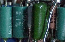
Isopropanol is a good flux solvent. I used a l.o.t of it rinsing this thing clean. don't want all those nasty stray capacitances/inductances around the 2M and 20M resistors eh?
Pictures once the circuit is tested, honest.
Isopropanol is a good flux solvent. I used a l.o.t of it rinsing this thing clean. don't want all those nasty stray capacitances/inductances around the 2M and 20M resistors eh?
Pictures once the circuit is tested, honest.
During testing, more problems were revealed with the amplifier circuitry. Troubleshooting required a known, low, DC voltage... I made a power supply. I also dug out the heater setup and came across a nice clamping setup... heated test bed looks like a sure thing from here.
still nothing is done. Photos when something is all the way working.
still nothing is done. Photos when something is all the way working.
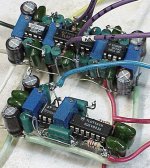
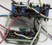
Progress! Working parts! Thank you Jesus!
After several hours in the cold, I have 3 working instrumentation amplifiers. The protoboard was NOT cutting it, with multiple instances of contacts not being made. I went dead-bug style and my problems were solved, along with the whole setup being more compact. The small power supplies I had were not cutting it, shutting down due to overcurrent... need to make ANOTHER power supply for the amps!
I'll be borrowing my work camera to take some photos tonight or tomorrow.
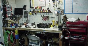
You guys will be amazed at the cleanliness of my bench...
After several hours in the cold, I have 3 working instrumentation amplifiers. The protoboard was NOT cutting it, with multiple instances of contacts not being made. I went dead-bug style and my problems were solved, along with the whole setup being more compact. The small power supplies I had were not cutting it, shutting down due to overcurrent... need to make ANOTHER power supply for the amps!
I'll be borrowing my work camera to take some photos tonight or tomorrow.
You guys will be amazed at the cleanliness of my bench...
WHAT! a big brush and it's all on the floor.You guys (and Gals) will be amazed at the cleanliness of my bench
Much tidier now.
okay smart guy...
compare this...
to this http://www.diyaudio.com/forums/attachment.php?s=&postid=1028467&stamp=1160681862
compare this...
to this http://www.diyaudio.com/forums/attachment.php?s=&postid=1028467&stamp=1160681862
Attachments
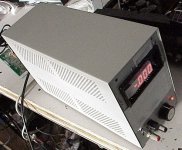
I actually made cleaning the bench Project priority #1 as I was building this: a low-voltage, controlled DC supply. 10-turns get me to about 2 volts under heavy load. Fewer turns for less. The circuit is highly derivative so I won't bother to post it. Mostly it's a pot setting a darlington transistor's Vbe, and the output is straight off the transistor. All parts free (thank God!). The knob says "offset" which is a neat touch.
case/transformer/ fused mains input: old UPS
meter: charged customer $250 to replace because of missing red plastic diffuser
output terminals: HP analog rms voltmeter
capacitors: adaptive vacuum controllers for semiconductor manufacturing chambers
pot: throttle valve for same
transistor: flow controller for same
heatsink: HP server power supply
knob: stage control for Olympus wafer inspection microscope station
you get the idea
Construction area: the chair, since the bench was completely FULL
now the bench has ONE project on it. A first.
Attachments
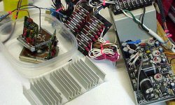
For those who voted for a heated test-bed, here is the progress of it so far: power supply candidate selected, heat sink selected, heaters in the bowl.
Need to decide on a temperature. Easy temperatures are 34C, 45C and 75C. The lower 2 have the advantage of me being able to safely handle them during operation.
remind me later about blowing up an opamp package with this power supply. I need to get back to work.
Need to decide on a temperature. Easy temperatures are 34C, 45C and 75C. The lower 2 have the advantage of me being able to safely handle them during operation.
remind me later about blowing up an opamp package with this power supply. I need to get back to work.
Attachments
- Status
- This old topic is closed. If you want to reopen this topic, contact a moderator using the "Report Post" button.
- Home
- Design & Build
- Parts
- Transistor Tester Current Levels