It's the thread that wouldn't die!
About the tester that wouldn't get built!
And I changed jobs, I'll be able to use a digital camera and show you guys what I'm talking about (yay! )
Well now it's time for something completely different. Pretty much everything I had already done is scrapped, because of one problem: amps flowing in wires, next to nanoamps flowing in wires. The chassis was too small.
I have a bigger chassis now and have redone several things that would have been difficult in the smaller space. The power supply for the meters is now a standalone 5V switcher on the "other" side of the noise filter for the transistor supply. The transistor supply has gone from a 50-ish VA 9VAC handwound job to a VERY nice 200-ish VA unit with just over 19V after rectification... If I decide to regulate it, there may still be enough to turn on a FET pretty hard. I don't think I'll have to regulate it because the capacitor filter went from 0.016F to 0.05F and there will likely be some smaller, closer caps as well. Discharging the caps with a DC fan is amusing for about a second and a half.
The displays have gone to all 4.5-digit meters (these were digital meters all along, now they are all the same meter). There is the possibility of a Mu-metal shield for the test voltages and meters. Testing will show whether or not that's necessary. Power is more like a bus for all 3 meters.
The power wiring is truly formidible (12AWG) for the currentls likely to be in use. There is now front-panel mounting room for ALL controls and fusing. Only the power input is in the back. Maximum current is looking like 5 or 6 amperes right now, depending on switch selection for the "GO" button. Foldback current limiting is looking like it may squeak in there.
Bracket is made for the PCBs for the panel meters. The capacitor bank is on a really tricky set of copper rings that I fabricated (it's not easy to tin a big, thick sheet of copper! ). There is a star grounding point now and EVERYTHING has at least one big ground wire to it.
I got a hefty pot that I'm going to try to use to set base current. We'll see if it cuts the mustard. I still may have to go with a custom pot, or at least buy one. The thermostatically controlled heatsink is on the short list for inclusion in the chassis proper also, possibly if room allows there will be 45 and 75 degree settings. If anybody is still reading this opus, who thinks I should go with what temperature, if I have to choose only one?
Pictures will be following soon, honest.
Total cost to date: $0.00 (thank God! )
How many years have I been working on this now? boo.
boo.
About the tester that wouldn't get built!
And I changed jobs, I'll be able to use a digital camera and show you guys what I'm talking about (yay! )
Well now it's time for something completely different. Pretty much everything I had already done is scrapped, because of one problem: amps flowing in wires, next to nanoamps flowing in wires. The chassis was too small.
I have a bigger chassis now and have redone several things that would have been difficult in the smaller space. The power supply for the meters is now a standalone 5V switcher on the "other" side of the noise filter for the transistor supply. The transistor supply has gone from a 50-ish VA 9VAC handwound job to a VERY nice 200-ish VA unit with just over 19V after rectification... If I decide to regulate it, there may still be enough to turn on a FET pretty hard. I don't think I'll have to regulate it because the capacitor filter went from 0.016F to 0.05F and there will likely be some smaller, closer caps as well. Discharging the caps with a DC fan is amusing for about a second and a half.
The displays have gone to all 4.5-digit meters (these were digital meters all along, now they are all the same meter). There is the possibility of a Mu-metal shield for the test voltages and meters. Testing will show whether or not that's necessary. Power is more like a bus for all 3 meters.
The power wiring is truly formidible (12AWG) for the currentls likely to be in use. There is now front-panel mounting room for ALL controls and fusing. Only the power input is in the back. Maximum current is looking like 5 or 6 amperes right now, depending on switch selection for the "GO" button. Foldback current limiting is looking like it may squeak in there.
Bracket is made for the PCBs for the panel meters. The capacitor bank is on a really tricky set of copper rings that I fabricated (it's not easy to tin a big, thick sheet of copper! ). There is a star grounding point now and EVERYTHING has at least one big ground wire to it.
I got a hefty pot that I'm going to try to use to set base current. We'll see if it cuts the mustard. I still may have to go with a custom pot, or at least buy one. The thermostatically controlled heatsink is on the short list for inclusion in the chassis proper also, possibly if room allows there will be 45 and 75 degree settings. If anybody is still reading this opus, who thinks I should go with what temperature, if I have to choose only one?
Pictures will be following soon, honest.
Total cost to date: $0.00 (thank God! )
How many years have I been working on this now?
boo.Holy Expletive Deleted! Photos!
First the simple part: the meters. 2 volt 4.5 digit red LED, with ultra-hifi custom wire extension (used to be at right angles to each other)
The plan is to mount these stacked on top of each other, and if noise from one to the next proves a problem (have to check after construction) then Mu-metal shielding can go between each board.
Attachments
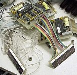
Chassis layout. Power is all on the left and can be separately shielded as required. Bridge rectifier has its own heatsink. The meter supply used to be a self-contained brick. Matching heasink came from same extrusion as the bridge's. Bracket holding the supply used to be the heasink on the output switch (! ). Capacitor bank is held together by the copper rings like I said before; it looks at a glance to be floating.
Caps came from the amp that used to be in this chassis
Transformer came from an old Nicolette oscilloscope
The display bracket needs to be mounted, it's just loose in there right now.
The Bourns 4W wirewound pot was just laying around here @ work, as was the power supply for the meters
The gold-colored mesh came from a Diebold Automatic Teller Machine IIRC
Power input filter came from a Dell server PSU
Attachments
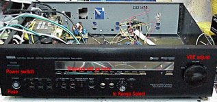
Front panel layout. Controls will mostly be along the bottom in a row. Displays should be lined up side-by-side. Power switch came with the chassis and switches only the hot side, then straight to the fuse. I'm not too worried about switching the neutral because of american wiring codes (neutral=earth at circuit breaker box) and the fact that polarity is inherently fixed in the type of power cord it'll be using (IEC standard plug, like everything else these days), which replaced the built-in 2-conductor power cable. The clear panel used to show all the cool features of the amplifier in this chassis. I sanded it down to about 600 grit, if that's not enough diffusion I'll get it to 400 or 220.
The fuse holder sits flush with the front panel, and came from an old HP DVM
The VBE adjust knob is from a Whitey pneumatic valve.
Range select switch came from a Tylan vacuum gage display, a nice Greyhill 6p2t
The fuse holder sits flush with the front panel, and came from an old HP DVM
The VBE adjust knob is from a Whitey pneumatic valve.
Range select switch came from a Tylan vacuum gage display, a nice Greyhill 6p2t
Attachments
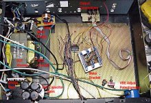
Displays are all working now. One was missing a digit so I un-rewired it. A different digit was out. Re-rewired it properly and all the digits were there. Meter boards bracket is mounted, partially wired in, sense resistors are mounted, partially wired in. Sanded the clear panel to 40 grit for a little bit of diffuser action, it's good enough.
Need to come up with some buffers. I didn't realize until last night that I was trying to compare a voltage with a +17VDC offset, and the meters need a max. 5VDC offset referenced to ground... no direct readings there.
Need to come up with some buffers. I didn't realize until last night that I was trying to compare a voltage with a +17VDC offset, and the meters need a max. 5VDC offset referenced to ground... no direct readings there.
As it happens, I have a magnetic 5V linear regulated supply that was built for this project but was scrapped in favor of the higher-current switching supply. It's based on a T0-220 monolithic regulator and the worst-case max. current for the three meters is only a few mA shy (990 out of 1000mA) of the max. of the regulator. I have been toying with the idea of lifting the earth connection to the switcher and seeing just how isolated the output is. Probably it would be simpler, with less risk of 
 action if I just installed a more substantial heastink on the linear supply and tested it at max. current for a while. I need to think about this some more. Wouldn't I have to lift the reference for each regulator that will supply a meter reading different voltages? in that case, it's 3 regulators but still easily to be had in my parts stores thank God.
I have also considered using op-amp buffers but they need their own power supply and that's back to the drawing board for a few minutes, with the additional interjection of noise from the buffer stage(s) (as you mentioned).
On a more positive note, the wiring is done for the sensing cell and decimal positions for the collector and base current, base voltage setting and output terminals. I am going to have to sleep on this a few days but as I type it seems more and more like I'm going to be having 3 regulators for 3 meters and then the current/regulator goes down and heatsinking is less problematic.
hmm...
Thanks for bearing with my slow work.")
action if I just installed a more substantial heastink on the linear supply and tested it at max. current for a while. I need to think about this some more. Wouldn't I have to lift the reference for each regulator that will supply a meter reading different voltages? in that case, it's 3 regulators but still easily to be had in my parts stores thank God.I have also considered using op-amp buffers but they need their own power supply and that's back to the drawing board for a few minutes, with the additional interjection of noise from the buffer stage(s) (as you mentioned).
On a more positive note, the wiring is done for the sensing cell and decimal positions for the collector and base current, base voltage setting and output terminals. I am going to have to sleep on this a few days but as I type it seems more and more like I'm going to be having 3 regulators for 3 meters and then the current/regulator goes down and heatsinking is less problematic.
hmm...
Thanks for bearing with my slow work.
Hi Stocker,
I think I saw an application all worked out in a FET handbook. It used an op amp and a fet, plus accurate resistors. One for sense, and another for output current sensing. Then a resistor to ground that developed a voltage scaled to your meter IC (2 or 0.2 volts FS).
-Chris
I think I saw an application all worked out in a FET handbook. It used an op amp and a fet, plus accurate resistors. One for sense, and another for output current sensing. Then a resistor to ground that developed a voltage scaled to your meter IC (2 or 0.2 volts FS).
-Chris
Chris if you could find that I'd be pretty happy (if it works for me I'd be happier! )
An engineer I know suggested that with care, a rail-splitter could be used, with an op-amp for a 'virtual ground'.
I would really like to be able to reference my meters to earth potential, because the earthing in this chassis seems very good to me.
An engineer I know suggested that with care, a rail-splitter could be used, with an op-amp for a 'virtual ground'.
I would really like to be able to reference my meters to earth potential, because the earthing in this chassis seems very good to me.
Hi Stocker,
Earth is a very relative thing. Your local "ground" reference can be hundreds of volts up and be fine. What's important is that the reference and measuring point not be noisy with respect to each other.
Free your mind of the one ground point concept.
I am looking, but this is on paper, in a book. I can't even remember which book. I just remember the general concept. I was considering using it at one point, and still may.
-Chris
Earth is a very relative thing. Your local "ground" reference can be hundreds of volts up and be fine. What's important is that the reference and measuring point not be noisy with respect to each other.
Free your mind of the one ground point concept.
I am looking, but this is on paper, in a book. I can't even remember which book.
I just remember the general concept. I was considering using it at one point, and still may.-Chris
Settled on a switch type for the front panel. Big (1") pushbutton. Replaceable contact block, with option for mounting another one...Allen Bradley, mmm...
Started cutting the front panels for it. Hard to do without making much noise because the rest of the family is asleep.
Helpful hint of the day? When drilling or cutting ferrous metals, affix a strong, small magnet near the tool, on the work piece. Keeps shavings from going as "all over the place" as without. Also, cleanup with a magnet is quick & easy: wave it around near the bench top & you're done. My magnet of choice is a neodymium one that came from a hard drive.
http://kabuki.eecs.berkeley.edu/~abo/papers/241/241_report.pdf
current mirroring, with additional concept of being able to use it for current going either way, which I would need. if I could find the circuit you mentioned that might be the way, but I was trying to keep the number of ESD-sensitive parts in this chassis down below one which sortof put FETs and opamps out of the picture. Maybe that will have to be set aside and I'll just be a little more careful with it.
The more I think about it, the more it looks like I'm going to have to redo the power supplies again. My engineer @ church said he did this once and got a good result... with a battery supply. doh.
How about this: a difference amplifier (FET opamp) driving a resistor to ground, or a calibrated resistive voltage divider if necessary...
hmmmm......again...
http://www.analogzone.com/acqt1222.pdf
http://www.wirelessnetdesignline.com/howto/wlan/193004145
wow it's late. I've linked these for whomever is still watching to see where I'm coming from, and so I can find them later when my brain is functional again.
hmmmm......again...
http://www.analogzone.com/acqt1222.pdf
http://www.wirelessnetdesignline.com/howto/wlan/193004145
wow it's late. I've linked these for whomever is still watching to see where I'm coming from, and so I can find them later when my brain is functional again.
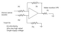
Moderate success. I rigged up a quick difference amplifier and plugged in an OP27. If the OP27 could swing up to V+ it would be a total victory. I need to dig through the opamps I have and see what can swing all the way up.
The tester circuit certainly works. I grabbed a random transistor and plugged it up and a base voltage of just over a volt caused a collector current of a couple of amperes.
Need to figure out how it will all work when I throw the reversing switch for doing PNP/P-ch. testing.
The tester circuit certainly works. I grabbed a random transistor and plugged it up and a base voltage of just over a volt caused a collector current of a couple of amperes.
Need to figure out how it will all work when I throw the reversing switch for doing PNP/P-ch. testing.
- Status
- This old topic is closed. If you want to reopen this topic, contact a moderator using the "Report Post" button.
- Home
- Design & Build
- Parts
- Transistor Tester Current Levels