Hi guys, I am realy an amateur at this still but nevertheless itis not stoped by a lack of ambition.
I got an old Blaupunkt tapedeck that I can use for housing my gainclone and its backbreaker transformer. It has 2 nice VU meter displays on the front. I don not know how to tell what rateing they they are so I decided I will try to copy as much as I can from the PCB to try and reconstruct this part of the circuit as a PCB module to my gainclone, afterall this way I get the parts free .
My knowledge of electronics is good enough to follow instructions basicaly and to start asking cute questions at this stage.
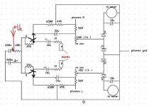
Here is what I have so far? am I right to assume there needs to be another stage before these transistors? (I realy know nothing about transistors except that they are kinda like valves)
The traces and jumpers gets very confusing quickly and I kinda got lost after I got this far, although I can see 2 more of these transistors and some resistors on another place on the PCB, I suppose thats the first stage...
A and B also represent leads I have not been able to chase down, do you think these are the inputs from the previous gain stage?
I noticed the phones output was connected to the VU circuitry is this common? (this tapedeck is 25 years old).
What does the 220uf caps do there with the 100r resistor?
where would the power leads connect?
Assistance on any of these will surely shorten the process alot.
PS the transistors are C945 which I assume are the same as KSC945
datasheet
I got an old Blaupunkt tapedeck that I can use for housing my gainclone and its backbreaker transformer. It has 2 nice VU meter displays on the front. I don not know how to tell what rateing they they are
so I decided I will try to copy as much as I can from the PCB to try and reconstruct this part of the circuit as a PCB module to my gainclone, afterall this way I get the parts free .My knowledge of electronics is good enough to follow instructions basicaly and to start asking cute questions at this stage.
Here is what I have so far? am I right to assume there needs to be another stage before these transistors? (I realy know nothing about transistors except that they are kinda like valves)
The traces and jumpers gets very confusing quickly and I kinda got lost after I got this far, although I can see 2 more of these transistors and some resistors on another place on the PCB, I suppose thats the first stage...
A and B also represent leads I have not been able to chase down, do you think these are the inputs from the previous gain stage?
I noticed the phones output was connected to the VU circuitry is this common? (this tapedeck is 25 years old).
What does the 220uf caps do there with the 100r resistor?
where would the power leads connect?
Assistance on any of these will surely shorten the process alot.
PS the transistors are C945 which I assume are the same as KSC945
datasheet
- Status
- This old topic is closed. If you want to reopen this topic, contact a moderator using the "Report Post" button.