Hello fellas!
I'm not in the mood these days for programming a uC, so was wondering for the several possibilities of making a Nixe thermometer.
One is a electromechanical approach where an analog needle thermometer directly activates eahc nixie cathode, and the other using an LM35, but interfacing it to the Nixie using common logic IC/discrete components is intriguing me.
Any thoughts?
Basic display schematic - is this ok?
Here's a display schematic using 4 LM3914.
The datasheet is badly explained as to more precise indications for the pins, so i used a voltage divider to setup more precisely the voltage roll-off points.
What's the general opinion? Is it ok?
The output transistors for the nixies are missing, as is the LM35, since they can be placed on a different place/board, and i could also use a LED/Nixie dual display thermometer.
Thank you to everyone.
PS: Can someone explain in layman terms how to use in a more correct way the LM3914?
Attachments
anything you can do with a PIC you can do with solder and a bunch of TTL -- but you will go insane in the process -- parenthetically I made my first impedance tester out of discrete TTL.
National has some Nixie driver schematics on their website.
I think that the Dallas Semi thermal devices might be easier to interface...
National has some Nixie driver schematics on their website.
I think that the Dallas Semi thermal devices might be easier to interface...
anything you can do with a PIC you can do with solder and a bunch of TTL -- but you will go insane in the process --
but it is fun to think in a different direction
")
The challenge to me AFAICT here is to be able to expand past the first bargraph/nixie "module".
Seems the higher next higher order module (eg"tens") unit would need to use its own output to step-shift the lower order's (eg"ones") "reference"/ground.
or just throw a bunch of TTL at the problem....
davesaudio said:
but it is fun to think in a different direction
The challenge to me AFAICT here is to be able to expand past the first bargraph/nixie "module".
Seems the higher next higher order module (eg"tens") unit would need to use its own output to step-shift the lower order's (eg"ones") "reference"/ground.
or just throw a bunch of TTL at the problem....
I should have referenced my statement to the actual author -- it was Steve Ciarcia who founded "BYTE" magazine back in the 1970's -- after McGraw Hill screwed up Byte, Steve began "Circuit Cellar" -- he referred to the process as "software in solder".
If you can get a student copy of Multisim (or a trial version) you may avail yourself of a powerful "logic tool" which will let you quickly cascade the analog data to logical output for the nixies. Three decimal digits isn't a big chore, so unless you are already going bonkers it shouldn't matter. Take two Prozac and call me in the morning.
Alright, here's a better picture.
This is just as basic as can be, a simple 40 LED thermometer using the LM3914. What bothers me is if the threshold of each LM3914 can be setup like on the schematic, with a voltage divider (at least it allows correct calibration of each stage).
To display it with Nixies:
The base of a high voltage transistor (MPSA-42) is connected through a resistor to each output of the LM3914.
So we get 1,2,3,4,5,6,7,8,9,0 for the first digit. When we want an extra digit, we interface a second MPSA42 to that output, controling the second nixie.
So we get: 1,2,3,4,5,6,7,8,9, 1 + 0
And so on with each stage.
Of course, one nixie needs 10 wires connecting it to each board(1,2,3,4,...), while the most significant nixie needs one wire for each board (giving 1,2,3,4).
Thus the scale is 0 to 40ºC, with 1ºC step (10mV per ºC, using the LM35), and can be represented by both displays, LED and Nixie.
PS: the schematic may be at fault regarding some connections and 3 missing components, but the general idea is there.
This is just as basic as can be, a simple 40 LED thermometer using the LM3914. What bothers me is if the threshold of each LM3914 can be setup like on the schematic, with a voltage divider (at least it allows correct calibration of each stage).
To display it with Nixies:
The base of a high voltage transistor (MPSA-42) is connected through a resistor to each output of the LM3914.
So we get 1,2,3,4,5,6,7,8,9,0 for the first digit. When we want an extra digit, we interface a second MPSA42 to that output, controling the second nixie.
So we get: 1,2,3,4,5,6,7,8,9, 1 + 0
And so on with each stage.
Of course, one nixie needs 10 wires connecting it to each board(1,2,3,4,...), while the most significant nixie needs one wire for each board (giving 1,2,3,4).
Thus the scale is 0 to 40ºC, with 1ºC step (10mV per ºC, using the LM35), and can be represented by both displays, LED and Nixie.
An externally hosted image should be here but it was not working when we last tested it.
PS: the schematic may be at fault regarding some connections and 3 missing components, but the general idea is there.
Simpleton said:....The base of a high voltage transistor (MPSA-42) is connected through a resistor to each output of the LM3914.
So we get 1,2,3,4,5,6,7,8,9,0 for the first digit. When we want an extra digit, we interface a second MPSA42 to that output, controling the second nixie.
So we get: 1,2,3,4,5,6,7,8,9, 1 + 0
And so on with each stage....
It will not work, IMO.
Sounds to me like you're trying to do this the hard way!
How about DS1620 -> EPROM -> one CD4028 per nixie
The EPROM in this case really gets used as a glue-logic look-up table to keep the parts count sane. You COULD put it together with about 100 pieces of TTL. Maybe less if you're clever (I admit, I haven't done the boolean algebra, and for nine inputs, I ain't doin' it, neither!
So, you take an EPROM with a nine-bit or better address bus (or just ignore the 9th bit if you're not worried about temps at the top end of the DS1620s scale), and at least four bits output per nixie you want to use. Program the EPROM in BCD.
Let's say you confine your temperatures to 8 bits of address, 16 bits of data. (Note: eprom outputs can be made "wider" by just paralleling 'em.. so, two 8bit x 8bit would work as well, etc).
Okay.
So, say the DS1620 outputs 0xEA at 30 degrees C.
So, you program address 0xEA with 0x0300.
When the DS1620 reads 0xEA, the data lines on the EPROM read 0x0300.
The high byte goes to one Nixie, the low byte to the other, and suddenly they read "30"! Oh yeah, of course, the CD4028 changes from BCD (EPROM data) to Nixie-lines for you.
As long as you have access to an EPROM burner, this is VERY easy! You could even change temperature scales (e.g. add fahrenheit) by adding more EPROMs in piggy-back and selecting which EPROM you want to use by the chip select line.
Wes
Dave,
Each lower order nixie pin (0-9) is connected to the four boards (1 MPSA for each board, independat from the others), so that when, for instance, a 1/11/21/31 is lit the "1" digit is also lit, with the higher order nixie (-,1/2/3) is lit by the corresponding decade board.
The LM3914 is driven in "dot" mode so that only a number is lit at a time,(i couldn't do it in "bargraph" mode).
I hope i could make myself understood, as i sometimes tend to complicated things a bit .
Moamps, when the cathodes of a nixie are driven by the commonly used MPSA42 via TTL levels, be it a CMOS/TTL device or a microcontroler (uC), a 33K - if memory doesn't fail me - resistor is connected betwen the chip an d the base of the transistor; colector to the nixie cathode and emitter to ground.
The LM3914, as stated on the datasheet, can drive both LED's adn transistors/logic at the same output at the same time.
Wes, i could also use a 74141/7441 chip and drive them directly.
You have a nice point there with the eprom thing. Actually, i don't have eprom burners 'cos i never had to use an eprom, but doing it the manual (hard) way with dip switches at the adresses could be fun too!
Hey, 74141 and 7441 are interesting -- they'll let you drop Nixie tubes right into almost any application intended for a 7447!
That said, you still have the problem of converting from ranged binary in the dallas part to BCD that those ICs require. An EPROM *is* a nice easy way to do that. .... alternatively, you could always learn to read the temperature in octal ....
You mentioned doing it the masochistic way... For what it's worth, EPROMs are basically arrays of diodes with some of the leads clipped for programming....
So, assuming you *could* find an EPROM programmer and suitable PROM -- you theoretically build this with a PCB having only four ICs. If the EPROM is big enough, you could even display in Fahrenheight, Kelvin, and Celcius. That would require X * 2 * 16 bytes of memory, where X is either 8 or 9, depending on the temperature range you want.
Actually, I just realized, if you ignored bit zero of the dallas part, you would never be out by more than half a degree, and could use the full range... So X = 8 will work *fine* for this app...A 27512 would do the job.
Somebody out there needs to start an online EPROM programming service...
Wes
That said, you still have the problem of converting from ranged binary in the dallas part to BCD that those ICs require. An EPROM *is* a nice easy way to do that.
.... alternatively, you could always learn to read the temperature in octal ....You mentioned doing it the masochistic way... For what it's worth, EPROMs are basically arrays of diodes with some of the leads clipped for programming....
So, assuming you *could* find an EPROM programmer and suitable PROM -- you theoretically build this with a PCB having only four ICs. If the EPROM is big enough, you could even display in Fahrenheight, Kelvin, and Celcius. That would require X * 2 * 16 bytes of memory, where X is either 8 or 9, depending on the temperature range you want.
Actually, I just realized, if you ignored bit zero of the dallas part, you would never be out by more than half a degree, and could use the full range... So X = 8 will work *fine* for this app...A 27512 would do the job.
Somebody out there needs to start an online EPROM programming service...
Wes
@£§$%!!!!!! 
Just figured one thing out: the LM3914 doesn't have high output levels. Stupid stupid stupid
Ok, Eprom time now (and i am a masochist, doing it the hard way is a great learning experience- and i can't do that in a uC).
Going to learn a bit on eproms now...
Oh well, c'est la vie!
Just figured one thing out: the LM3914 doesn't have high output levels. Stupid stupid stupid
Ok, Eprom time now (and i am a masochist
, doing it the hard way is a great learning experience- and i can't do that in a uC).Going to learn a bit on eproms now...
Oh well, c'est la vie!
Simpleton said:...Oh well, c'est la vie!... [/B]
One idea:
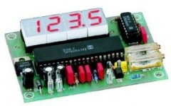
Tweaking Conrad module based on KTY, ICL7107 (20euro).
Regards,
Milan
Attachments
- Status
- This old topic is closed. If you want to reopen this topic, contact a moderator using the "Report Post" button.
- Home
- Design & Build
- Parts
- Hybrid thermometer with Nixies