Hiya,
I'm hoping one of you guys can give me a hand with a project im working on. after browsing the forums it seems like it should be pretty easy for you. Ive made some regular electronic projects but im pretty new to audio electronics.
Basicaly i have a problem where i have lot of audio outputs from various sources such as DVD player, VHS player, TV, PS2, Laptop, Desktop, Stereo. and have a good few inputs such as Surround sound, Headset, Wireless headphones, TV etc etc. At the moment i am constantly crawling under and behind my desk when i want to change what im hearing and how.
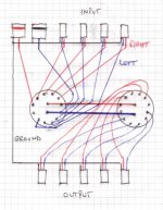
So, I have come up with the idea of having an audio junction box, where i have a plastic enclosure box, on one side i have a row of inputs phono and 3.5mm jack, and on the other side I have a row of 3.5mm outputs, all of which has its own switch so i can turn in/outputs on and off.
Here is a picture of the basic layout, but im not sure of what it will do to the sound quality and if i need some sort of op amp or what.
I'm hoping one of you guys can give me a hand with a project im working on. after browsing the forums it seems like it should be pretty easy for you. Ive made some regular electronic projects but im pretty new to audio electronics.
Basicaly i have a problem where i have lot of audio outputs from various sources such as DVD player, VHS player, TV, PS2, Laptop, Desktop, Stereo. and have a good few inputs such as Surround sound, Headset, Wireless headphones, TV etc etc. At the moment i am constantly crawling under and behind my desk when i want to change what im hearing and how.
So, I have come up with the idea of having an audio junction box, where i have a plastic enclosure box, on one side i have a row of inputs phono and 3.5mm jack, and on the other side I have a row of 3.5mm outputs, all of which has its own switch so i can turn in/outputs on and off.
Here is a picture of the basic layout, but im not sure of what it will do to the sound quality and if i need some sort of op amp or what.
An externally hosted image should be here but it was not working when we last tested it.
Just connect your inputs to a rotary switch and your outputs to one as well.
2 pole 6 position break before make like these will do the job.
http://www.altronics.com.au/index.asp?area=item&id=S3022
Inputs to the outside connectors (input sw) > out from the inside 2 connectors (input sw) > inside 2 connectors (output sw) > outside connectors (output sw)
Better than having individual switches that you can forget to turn off and have 4 sources playing at once.
Ok,
I've never used rotary switched before and am not certain how they work, is this what you mean and how they work?
I've never used rotary switched before and am not certain how they work, is this what you mean and how they work?
An externally hosted image should be here but it was not working when we last tested it.
Keep your left channel to 1 pole and right channel to the other pole. You've got the idea but make sure you don't join the RCA inputs as you have shown.... treat it the same as the 3.5mm jacks.
All the grounds on the inputs and outputs are joined together at 1 point and bypass the switches.... only hot wires on the switches.
All the grounds on the inputs and outputs are joined together at 1 point and bypass the switches.... only hot wires on the switches.
Keep your left channel to 1 pole and right channel to the other pole. You've got the idea but make sure you don't join the RCA inputs as you have shown.... treat it the same as the 3.5mm jacks.
All the grounds on the inputs and outputs are joined together at 1 point and bypass the switches.... only hot wires on the switches.
Hmm, Not really sure what you mean. should the RCA have their own switch in that case?
And do you mean all the ground wires should connect together not touching the switches?
Ok, im off to maplins this afternoon to pick up the parts, heres what im going to get, please correct me if I'm missing anything or bits are wrong...
Switches x 2
knobs x 2
Enclosure x 1
3.5mm Jacks x 9
Phono connectors x 2
Switches x 2
knobs x 2
Enclosure x 1
3.5mm Jacks x 9
Phono connectors x 2
Splash said:
Hmm, Not really sure what you mean. should the RCA have their own switch in that case?
And do you mean all the ground wires should connect together not touching the switches?
What I mean is that you only connect the centre pin of the RCA to the switch.... same as the 3.5mm.
Ground wires by pass the switch all together and all connect to 1 point.
Ah ok, Think im with you now  made another quick diagram just to make sure....
This right?
made another quick diagram just to make sure....This right?
An externally hosted image should be here but it was not working when we last tested it.
Splash said:Ah ok great, wasent expecting 3 pins on the 3.5mm jacks,
Thanks alot
Yup, the 3.5's will need to be stereo for this application.
No in fact the two that have continuity are the same "pin" since they are connected together, and the other one is the other pin. The reason that there are 3 pins on the package is just to make it more mechanically secure once soldered in place.Splash said:Ah ok, 2 of them have continuity so im guessing the other one is dummy?
Another possibility is that the extra pin is connected to the signal pin only when nothing is plugged into the jack. The connection is broken once a plug is inserted. This type of jack is often used to turn off a built-in speaker when a headphone is plugged in.
Sorry to say it, but you really can't make this work with mono jacks.
- Status
- This old topic is closed. If you want to reopen this topic, contact a moderator using the "Report Post" button.
- Home
- Design & Build
- Parts
- Need help with simple project