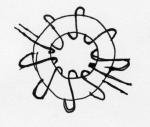
My question is this: when winding the center tapped primary on the transformer, and say I was going to have 8 total turns, would I wind 4 all the way around the torroid and another 4 all the way around, or just 8 all the way around once?
The link to the page is:
http://sound.westhost.com/project89.htm
But it doesnt answer this particular question and I can see his example transformer well enough ...perhaps someone else has some coil winding experience.
Thanks,
A.H.
The link to the page is:
http://sound.westhost.com/project89.htm
But it doesnt answer this particular question and I can see his example transformer well enough ...perhaps someone else has some coil winding experience.
Thanks,
A.H.
Sorry to be contradictory HBarske, but it would in fact be better if the two halves of the primary were wound bifilar, i.e. the two wires wound side by side at the same time. This will reduce the drain voltage overshoot as each fet turns off because the opposite winding will clamp the voltage more effectively. Spreading the winding around the full circumference of the core will be beneficial for cooling if nothing else. There is also something to do with proximity effect where the magnetic field pushes the current over to one side of the wire; this is minimised by spreading out the turns. Don't really understand that part but I have heard others talk about it.
Where the page says "then the secondary over it in the *opposite* direction, to maximise inter-winding coupling.", this is pure nonsense. Wind it the same direction as the primary.
That example of a commercially made transformer in the picture - wow! talk about rough! Someone should be hanging their head in shame!
GP.
remember to note the polarity of the windings
1) the SG3525 isn't exactly the lowest noise PWM switcher on the planet. I suppose that this doesn't matter since the amp is used in an automobile with high ambient noise.
2) you can simplify the design by driving the switching transistors with a diode, even an 1n4148, and tie the gates to ground through a 220 ohm resistor -- this will make sure they are truly off when they are supposed to be off.
3) the SG3525 has the option of "soft-start". I don't know why the author didn't use it.
4) it's a good idea to use a variable resistor, or a resistor pair to set Rt -- I have found that the switching frequency can be audible with the SG3525 -- more a problem in robotics than in this application, but good to know.
5) If you are using a "no-name" torroid, before you wind the transformer, you should "characterize" the torroidal core. You do this with an LCR meter -- find the inductance with 10 turns of wire (you can use #28 wire!). The inductance index is then:<p>
A(L) = 10,000 * L (uH) / N^2
The required impedance of the inductor is inversely related to frequency and load. Characterizing the torroid will at the minimum, prevent you from using a completely inappropriate core.
6) 3300uF is bit "overkill" for a power supply operating at 35kHz when you consider that you have millivolts of swithing noise and ambient noise -- make sure, however, to use low ESR caps designed for switching supplies --
7) I suppose that the resistor from VRef to the non-inverting input is some form of current limitation. Usually a resistive divider is used to adjust the non-inverting input.
9) Some RFI protection (in the name of some ferrites or a choke capable of handling 3 Amps) on the output would be nice. The switching transients merely glance at the filter capacitors, wave adieu and say "a bientot" before they are on their merry way down to the amplifier. Oh, and while you're at it, put some ferrites on the battery line also -- switching transients will go anywhichway.
8) mount the entire power supply in a salvaged PC power supply case. No kidding. Things can and do go wrong with switching power supplies (although I don't know if it exists, there should an addendum to Murphy's law which would describe the rate of catastrophic failure as exponentially related to the load current.)
My question is this: when winding the center tapped primary on the transformer, and say I was going to have 8 total turns, would I wind 4 all the way around the torroid and another 4 all the way around, or just 8 all the way around once?
The link to the page is:
Switchmode Power Supply For Car Audio
But it doesnt answer this particular question and I can see his example transformer well enough ...perhaps someone else has some coil winding experience.
Thanks,
A.H.
Do it this way, wind 4 turns on half of the core, centre tap, and wind the other 4 turns on the remaining half. These will be your primary turns. Wind the secondaries on top of the primary turns in a similar fashion.
SG3525 doesn't have any moving parts
The SG3525 doesn't have any moving parts because its an IC so it won't be noisy. The noise which is caused by some switching frequencies is usually caused when the strands of wire are not twisted together tightly or not at all when more than 1 strand is used. I have been using the SG3525 many times both with toroids and the etd39 cores and have never experienced noise from the switching frequency since I started to twist the strands. If you experience a problem with noise after the twisting then you can either use varnish or epoxy resin to hold the windings in place.
1) the SG3525 isn't exactly the lowest noise PWM switcher on the planet. I suppose that this doesn't matter since the amp is used in an automobile with high ambient noise.
2) you can simplify the design by driving the switching transistors with a diode, even an 1n4148, and tie the gates to ground through a 220 ohm resistor -- this will make sure they are truly off when they are supposed to be off.
3) the SG3525 has the option of "soft-start". I don't know why the author didn't use it.
4) it's a good idea to use a variable resistor, or a resistor pair to set Rt -- I have found that the switching frequency can be audible with the SG3525 -- more a problem in robotics than in this application, but good to know.
5) If you are using a "no-name" torroid, before you wind the transformer, you should "characterize" the torroidal core. You do this with an LCR meter -- find the inductance with 10 turns of wire (you can use #28 wire!). The inductance index is then:<p>
A(L) = 10,000 * L (uH) / N^2
The required impedance of the inductor is inversely related to frequency and load. Characterizing the torroid will at the minimum, prevent you from using a completely inappropriate core.
6) 3300uF is bit "overkill" for a power supply operating at 35kHz when you consider that you have millivolts of swithing noise and ambient noise -- make sure, however, to use low ESR caps designed for switching supplies --
7) I suppose that the resistor from VRef to the non-inverting input is some form of current limitation. Usually a resistive divider is used to adjust the non-inverting input.
9) Some RFI protection (in the name of some ferrites or a choke capable of handling 3 Amps) on the output would be nice. The switching transients merely glance at the filter capacitors, wave adieu and say "a bientot" before they are on their merry way down to the amplifier. Oh, and while you're at it, put some ferrites on the battery line also -- switching transients will go anywhichway.
8) mount the entire power supply in a salvaged PC power supply case. No kidding. Things can and do go wrong with switching power supplies (although I don't know if it exists, there should an addendum to Murphy's law which would describe the rate of catastrophic failure as exponentially related to the load current.)
The SG3525 doesn't have any moving parts because its an IC so it won't be noisy. The noise which is caused by some switching frequencies is usually caused when the strands of wire are not twisted together tightly or not at all when more than 1 strand is used. I have been using the SG3525 many times both with toroids and the etd39 cores and have never experienced noise from the switching frequency since I started to twist the strands. If you experience a problem with noise after the twisting then you can either use varnish or epoxy resin to hold the windings in place.
- Status
- This old topic is closed. If you want to reopen this topic, contact a moderator using the "Report Post" button.
- Home
- Design & Build
- Parts
- SMPS Elliott Project 89--Winding Xformers