Hi,
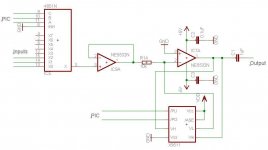
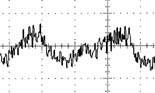
I have a problem with a circuit that I'm working with. There are some inputs on a 4051 switch (+/- 5V), output to a non-inverting buffer and an inverting op that work as an attenuator with a digital pot (controlled by a PIC). If I use a sinus wave (0.4V, 2kHz) on as input I get a very noisy and "unstable" (on an oscilloscope) output. The picture I attached is not from my output but it looks similar.
I'm sure the problem is the X9511 (10k) because if I disconnect it and use a normal resistor instead (for example 5k) the output is half the input and it's the same "shape" and frequency on the output.
Is it my design that isn't correct or could it be something else? I'm also interested in other ways how to improve the circuit except for the noise.
Fredrik
Attachments
Looks like you have "clock noise" from the PIC coupling onto the NE5532's etc. -- decouple the supply pins of the OP-AMPs, multiplexer and digital pot with 100nF ceramic and 1 uF tantalum capacitors. Also -- the MUX address and Digital Pot control pins -- you can feed these with a 10K resistor in series -- this will decouple a lot of noise from the PIC. Be careful with layout --
Thanks for your answer. I added resistors on the signals from the PIC and I it helped some. I also noticed that my DC supply wasn't very "clean" so I put capacitors (all I had was polyester) to the ground from +/- 5V which helped a lot.
In my circuit I use the same +5V for all chips and a -5V for the OP's and the MUX (VEE). Do I have to decouple all the supply pins or isn't it enough to do it once at the +/- 5V supply since they're all linked together? Why use tantalum capacitors?
How is the "clock noise" transmitted to the other circuits? Through ground?
Thanks again,
Fredrik
Ayah said:Thanks for your answer. I added resistors on the signals from the PIC and I it helped some. I also noticed that my DC supply wasn't very "clean" so I put capacitors (all I had was polyester) to the ground from +/- 5V which helped a lot.
In my circuit I use the same +5V for all chips and a -5V for the OP's and the MUX (VEE). Do I have to decouple all the supply pins or isn't it enough to do it once at the +/- 5V supply since they're all linked together? Why use tantalum capacitors?
How is the "clock noise" transmitted to the other circuits? Through ground?
Thanks again,
Fredrik
Each of the +/-V pins of the analog AND digital components should be bypassed -- it isn't sufficient to bypass the supply alone. the traces themselves will pick up radiated energy from the micro-processor. while you can't hear it, the radiated energy is sometimes sufficient to cause opamps to behave in a less than ideal way.
The switching speed of the PIC may not be high enough for it to matter (are you using 4MHz or 20MHz?) but a ceramic seems to be preferred to polyester film in this application and they are cheap. using a tantalum or aluminum electrolytic is a bit of "belt and suspenders".
One last thing -- I believe that the NE5532 will operate with lower noise and THD if the supply voltage is higher. There are families of devices that are designed to work with 3.3V or 5V, but the NE5532 isn't of that generation. If you are committed to the NE5532 that's OK, it is a much venerated opamp
")
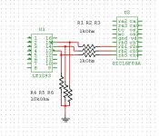
another thing -- see the attached JPEG -- you might find this method of coupling the PIC to your MUX and POT works even better.
btw, there is a good thread with some knowledgeable (SP?) guys on multilayer ground planes. since you have mixed analog-digital you should hop on board.
http://www.diyaudio.com/forums/showthread.php?s=&postid=665245#post665245
Attachments
Those Xicor 95 series pots use an on-chip substrate bias generator (charge pump) and are as noisy as all hell.
You are better off using a pot designed for audio (quiet) like a Dallas DS1267 or subsequent versions thereof. There are many others by other makers as well, but the Xicor is easily the worst.
M
You are better off using a pot designed for audio (quiet) like a Dallas DS1267 or subsequent versions thereof. There are many others by other makers as well, but the Xicor is easily the worst.
M
I can see one likely source of trouble with your circuit: the inverting opamp can be operated with a gain of less than 1 (depending on the pot value of course). This is may cause it to be unstable, and oscillate, which can produce an output much like what you are seeing. Is there any particular reason why you chose to use the pot to vary the gain of the amp, rather than simply to attenuate the signal?
I'd recommend using the digital pot as a variable attenuator between the non-inverting buffer, and the inverting amp (connect VH as input, VL grounded, and W as output). Select the gain of the inverting amp to give you the desired maximum output level with the pot at maximum output.
If the pot has a linear taper rather than log, you can approximate a log taper by putting a resistor (equal to 1/5 to 1/10 of the pot resistance) between the VH and VL terminals.
I would recommend putting a 10 to 22 ohm resistor in series with the power supply pins of each component. Make sure to use bypass capacitors after these resistors, as close as possible to each device's power supply pins. This forms an RC filter which will help keep digital noise out of the power supplies. You'd be surprised how well this can work.
- Status
- This old topic is closed. If you want to reopen this topic, contact a moderator using the "Report Post" button.
- Home
- Design & Build
- Parts
- Noise with a digital pot (X9511)