This is a call to all the forum members that have a knowledge of transformer design. You guys are in here I have read snippets of information posted from time to time.
What Is being tried is a copy of a design shown here.
I have been in contact with Arto Kolinummi (one of the co-designers ) and asked him if he would mind an attempt at reverse engineering the full range transformer that he and a friend created. HE said go for it!
http://www.ele.tut.fi/~artoko/audio/audioindex.html
Check out the full range transformer section.
From what I can gather the trannie is constructed iin a manner that permits it to have a wide frequency response into a capacitive load ( those big ESL panels )
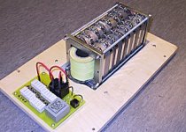
As a step up trannie does effect the sound of an ESL it's surprising how many designs stand on the shoulders of others. What they did was actually legitimate design and engineering. The actual design and engineering work is above my current knowlege of transformers. I'm not familiar with the techniques of interleaving and so forth. Maybe someone could direct me to a good source book. But the actual winding is probably within my capabilities. But I'm pretty sure that there are members that could take a stab at it. A basic question is what kind of ferrite for is used for the core? THe circuit board in the front of the picture is the HV bias supply nothing to do with the trannie.
Thanks!
Mark
What Is being tried is a copy of a design shown here.
I have been in contact with Arto Kolinummi (one of the co-designers ) and asked him if he would mind an attempt at reverse engineering the full range transformer that he and a friend created. HE said go for it!
http://www.ele.tut.fi/~artoko/audio/audioindex.html
Check out the full range transformer section.
From what I can gather the trannie is constructed iin a manner that permits it to have a wide frequency response into a capacitive load ( those big ESL panels )
As a step up trannie does effect the sound of an ESL it's surprising how many designs stand on the shoulders of others. What they did was actually legitimate design and engineering. The actual design and engineering work is above my current knowlege of transformers. I'm not familiar with the techniques of interleaving and so forth. Maybe someone could direct me to a good source book. But the actual winding is probably within my capabilities. But I'm pretty sure that there are members that could take a stab at it. A basic question is what kind of ferrite for is used for the core? THe circuit board in the front of the picture is the HV bias supply nothing to do with the trannie.
Thanks!
Mark
Attachments
Here is what I have so far from Arto:
MARK KRAVCHENKO wrote:
Hello Arto!
I am putting together the parts needed to clone your full range esl. Would you allow me to post a questiojn on the DIYaudio forum about how it may be possible to clone the stepup transformer? I understand that you were a part of the design so I wanted to ask your permission first if that is possible. I think that next to the surface area, the insulation and the resistive treatment the stepup transformer is the biggest part of determining the sound quality of the speaker.
Mark
Hi
As you may have read from my wep page, transformer made a huge difference to sound with this particular panel. Most transformers are not really suitable for full range use. Even when panel is so large it still requires some dipole equalization and signal amplitudes can be very high at low frequencies. Distortion increases much before core saturation so transformer should be designed so that there is enough headroom.
I was confident earlier that high low frequency harmonic distortion that causes severe intermodulation distortion at higher frequencies was the reason to the differencies that were heard, but now when I have measured several tube amplifiers and their output transformers I am not so confident anymore. Normally high distortion at low frequencies tend to make sound warmer not colder and irritating like it was the case with earlier transformers used with Portal fullrange.
We have decided not to share exact winding details of that transformer. It requires some inductance and capacitance optimization to be made on order to get it work well with so wide bandwidth and that may not be possible with simple interleaving techniques. I recommend to use high performance insulators with low dielectric values such as teflon and to minimize primary resistance. Transformer transforms voltage with low distortion but currents are not linearly transformed. That is why any extra resistance is bad in primary side.
I have nothing against posting questions to DIYaudio forum. I hope that you are able to finish the project and are satisfied with the results. It required a lot of optimization time for me before I was satisfied but I have been satistified with them for amazingly long time. But nothing is forever and new plans are waiting for implementation.")
Arto
MARK KRAVCHENKO wrote:
Hello Arto!
I am putting together the parts needed to clone your full range esl. Would you allow me to post a questiojn on the DIYaudio forum about how it may be possible to clone the stepup transformer? I understand that you were a part of the design so I wanted to ask your permission first if that is possible. I think that next to the surface area, the insulation and the resistive treatment the stepup transformer is the biggest part of determining the sound quality of the speaker.
Mark
Hi
As you may have read from my wep page, transformer made a huge difference to sound with this particular panel. Most transformers are not really suitable for full range use. Even when panel is so large it still requires some dipole equalization and signal amplitudes can be very high at low frequencies. Distortion increases much before core saturation so transformer should be designed so that there is enough headroom.
I was confident earlier that high low frequency harmonic distortion that causes severe intermodulation distortion at higher frequencies was the reason to the differencies that were heard, but now when I have measured several tube amplifiers and their output transformers I am not so confident anymore. Normally high distortion at low frequencies tend to make sound warmer not colder and irritating like it was the case with earlier transformers used with Portal fullrange.
We have decided not to share exact winding details of that transformer. It requires some inductance and capacitance optimization to be made on order to get it work well with so wide bandwidth and that may not be possible with simple interleaving techniques. I recommend to use high performance insulators with low dielectric values such as teflon and to minimize primary resistance. Transformer transforms voltage with low distortion but currents are not linearly transformed. That is why any extra resistance is bad in primary side.
I have nothing against posting questions to DIYaudio forum. I hope that you are able to finish the project and are satisfied with the results. It required a lot of optimization time for me before I was satisfied but I have been satistified with them for amazingly long time. But nothing is forever and new plans are waiting for implementation.
Arto
BAck to the books
I guess there is no one interested in this topic.
I'll do what I can and do some net trawling to see if there are any related sites for audio transformers. Because that is what this basically is. Just in reverse and wound in such a way to minimise inductance as it is feeding a rather high capacitive load. I'm guessing that a normal transformer winding method would combine with the ESL panel capacitance and for a low pass filter to low to get clear highs.
Mark
Mark, I've been planning to do ESL transformers, too. One of many projects for the summer. I'll be using EI cores salvaged from 12 volt, 120 VA power transformers.
I've looked at toroids and the transformer you pictured, but both seemed too hard for this DIY'er.
If you haven't tried it yet, have a look at the OPT Design Assistant software from Yvesm. It will give you an estimate of number of turns, wire size, and much more. Very impressive work from Yvesm.
Here are some more links for you:
http://www.geofex.com/Article_Folders/xformer_des/xformer.htm
http://www.turneraudio.com.au/htmlwebpgs02/outputtrans.htm
I'll be using EI cores salvaged from 12 volt, 120 VA power transformers.I've looked at toroids and the transformer you pictured, but both seemed too hard for this DIY'er.
If you haven't tried it yet, have a look at the OPT Design Assistant software from Yvesm. It will give you an estimate of number of turns, wire size, and much more. Very impressive work from Yvesm.
Here are some more links for you:
http://www.geofex.com/Article_Folders/xformer_des/xformer.htm
http://www.turneraudio.com.au/htmlwebpgs02/outputtrans.htm
Hi,
I'm not a transformer geek but does it matter that the load is essentially a capacitor? Your va loading will increase but so what.
Is the core really ferrite? Could it be iron? Silicon iron for power, what iron for full range?
Is the core split to allow the bobbins to slide on after winding?
Is that why the bolts clamp it all back together again?
If it is a split core is there a way to test the magnetic circuit to determine the gap or small enough gap after bolting?
Keep the questions flowing; it gives room for directed research.
Finally is your ESL really full range or is it separate panels?
Answers with what little I know
Yes the load is basically a big capacitor. THe cores in the picture are split to allow the bobbin to be inserted. It is also true that the load the transformer sees being capacitive will cause a reactance ( a little fuzzy on this part actually ) that will basically increase the load to the tranny as the frequency goes down. Hence the note from Arto that they went through great pains to design a trannnie that was very low in it's self inductance. ( Agin I think this is somewhat true ) My only guess is a type of bifiliar winding. I really don't know enough about the subject yet. But with the posts coming it may all fall into place.
THe loudspeaker is divided up into three fullrange panels not segmented as woofer, mid tweeter. There is a lot of surface area there and from what Arto has told me he does not need a sub. All I can say is cool!
More questions:
Reasoning things this way. Arto wound torroids himself. And they had an amp output trannie for a while. I'm guessing that they are harder to wind. He said that the sound was harsh. I have read something similar on Sheldon Stokes website. He claimed it was transformer ringing and cured it with an appropriate resistor. What gives here? Second I too have some big momma I E core transformers and wonder if the same performance could be extracted from such a beast. THey are huge isolation transformers at least 1500 VA or better from some of the tables I have seen.
If they are no good then next question is:
Anybody know where to get the ferrite cores? I've never purchased ones that big. And I guess the bobbins would need to be sourced for either option.
MArk
I'm not a transformer geek but does it matter that the load is essentially a capacitor? Your va loading will increase but so what.
Yes the load is basically a big capacitor. THe cores in the picture are split to allow the bobbin to be inserted. It is also true that the load the transformer sees being capacitive will cause a reactance ( a little fuzzy on this part actually ) that will basically increase the load to the tranny as the frequency goes down. Hence the note from Arto that they went through great pains to design a trannnie that was very low in it's self inductance. ( Agin I think this is somewhat true ) My only guess is a type of bifiliar winding. I really don't know enough about the subject yet. But with the posts coming it may all fall into place.
THe loudspeaker is divided up into three fullrange panels not segmented as woofer, mid tweeter. There is a lot of surface area there and from what Arto has told me he does not need a sub. All I can say is cool!
More questions:
Reasoning things this way. Arto wound torroids himself. And they had an amp output trannie for a while. I'm guessing that they are harder to wind. He said that the sound was harsh. I have read something similar on Sheldon Stokes website. He claimed it was transformer ringing and cured it with an appropriate resistor. What gives here? Second I too have some big momma I E core transformers and wonder if the same performance could be extracted from such a beast. THey are huge isolation transformers at least 1500 VA or better from some of the tables I have seen.
If they are no good then next question is:
Anybody know where to get the ferrite cores? I've never purchased ones that big. And I guess the bobbins would need to be sourced for either option.
MArk
My experience is probably irrelevant here but i'll share it anyway. During my electrostatic period (1984-1988) i worried a lot about the quality of transformers. The ones i used were all home-wound and at best did not spark too much. I tried various sizes (50-300VA cores) and never noticed too big differences. I also had some iron from a Quad 57 and it sounded remarkably close to my home-grown efforts. The panels allowed for either full range or split operation. In full range mode there was a predictable absence of high frequencies - way too much capacitance which neither the transformers, nor amps liked too much. It was possible to find a combination of directly driven thin segments and segments with reduced (just series resistors) HF which would result reasonably balanced sound.
Eventually i obtained very good sound by going for quantity rather than quality - i used a separate transformer for each crossover region - 3 per speaker. Even better was using separate amps as well.
Thinking about it now i honestly don't believe that a single tranformer/panel can be made to sound good without a lot of EQ. It may be built inside the transformer parameters but it's got to be there.
A studying I go!
So now I have copy of the Radiotron Designers handbook. Iam reading and re-reading the chapter on transformer design. Some of Arto's statements now make more sense. And some of the statements from this forum are making sense. Some don't. Such as the "Not possible to design a fullrange transformer" THere are frequency rsponse graphs on Arto's site. It looks fullrange to me!
Moray thanks for the post and the patent number. I have downloaded it and converted it to a PDF file will print it out and read it some more. It is as cryptic as all other patents untill I understand more about the nuances of transformer design.
I will have more questions about insulation types and winding interleaving to combat capacitance and inductance. I have some ideas. Also does anyone know where to get bobbins and the like in Canada?
MArk
Very interesting!
I just read through the Strickland patent and it does sound very interesting indeed. THe idea of circumventing the problems of high inductance that starves the high end are particularly well thought out. If I understand correctly he combined the two transformers with a second order filter. And incorporated built-in frequency equalisation. To read it there appears to be a practical possibility that this design would solve many of the problems of a full range design.
The patent also hinted to the possibility of making a conventional transformer that woulf pass fullrange signal. Mr. Strickland rightfully stated that it would be large and expensive. Se the size of Arto's transformer. I'm guessing that is the design path that group followed. More questions and ideas are formulating. A little knowledge is a dangerous thing!
MArk
- Status
- This old topic is closed. If you want to reopen this topic, contact a moderator using the "Report Post" button.
- Home
- Design & Build
- Parts
- Help in designing a full range ESL transformer PLEASE!