I have read the excellent threads on rewinding a microwave oven transformer (MOT) to become either a big choke or a high voltage power transformer.
My question is more about the brief references to just using it without rewinding as a choke for low current applications.
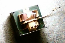
The following picture is of an MOT I pulled out of the oldest, heaviest microwave I've ever seen. The primary measures less than 1R, there are a few turns of insulated wire between primary and secondary bobbins that measure as a dead short, and the secondary measures about 58R, however one end is grounded.
So can this be used as a choke for a 100mA PS? TIA.
My question is more about the brief references to just using it without rewinding as a choke for low current applications.
The following picture is of an MOT I pulled out of the oldest, heaviest microwave I've ever seen. The primary measures less than 1R, there are a few turns of insulated wire between primary and secondary bobbins that measure as a dead short, and the secondary measures about 58R, however one end is grounded.
So can this be used as a choke for a 100mA PS? TIA.
Attachments
Hell, use it up to 500mA. Gap the core properly, and disconnect the secondaries (BTW, the insulated wire is for the 3.15V 20-50A or so filament in the magnetron).
If you have two, you might remove the windings from both and put the primaries on one (for a 10A isolation transformer") ) and secondaries on the other, in series, for your choke.
) and secondaries on the other, in series, for your choke.
Say, anyone ever measure the inductance of one of those?
Tim
If you have two, you might remove the windings from both and put the primaries on one (for a 10A isolation transformer
) and secondaries on the other, in series, for your choke.Say, anyone ever measure the inductance of one of those?
Tim
I've never seen a meter that measures R's, so I do not know what you mean when you say the secondary measures 58 of them, or where you got your meter. An ohmmeter will be immensely useful for such a measurement however. The resistance readings will be in ohms though, not R's. Some lazy people here dislike that I insist on calling an ohm an ohm. Tough. To them I'll state my local temperature in degrees T.
That wasn't aimed specifically at you. You might be an innocent bystander that has seen other dummies use this incorrect nomenclature. Assenine practises have no chance of disappearing if no-one says anything.
Now that I got that off my chest, yes the transformer as-is may work quite well as your choke. You can llift the grounded end of the HV winding, or leave it connected to the frame and isolate the frame if needed. The in-between winding is a 3.15 volt filament winding for the magnetron filament. I have employed them successfully as chokes for breadboarded B+ supplies to valve output stages as high as 500 mA. For more L you can series the primary with the secondary, For less you can anti-series (opposing phase) the two windings.
There are many creative uses for salvaged microwave oven transformers, often called MOT's. I must have 50 of them by now. The magnetrons can source two awesome fridge magnets as well.
I seem to recall seeing about 17-20 Henries in the HV winding with no core gap. I have not experimented yet with adding a gap.
rcavictim said:I've never seen a meter that measures R's, so I do not know what you mean when you say the secondary measures 58 of them, or where you got your meter.
R = Resistance = Ohms
AudioFreak said:
R = Resistance = Ohms
Pretty cold here tonight Dan. -10T.
T=temperature

rcavictim said:I've never seen a meter that measures R's, so I do not know what you mean when you say the secondary measures 58 of them
Screw you. If I'm too lazy to type o-h-m I'll use shift-r too.
R is the standard schematic shorthand for European schematics. I suppose you also gripe about people using 0R22 and nanofarads.
That wasn't aimed specifically at you. You might be an innocent bystander that has seen other dummies use this incorrect nomenclature. Assenine practises have no chance of disappearing if no-one says anything.
The only thing that I hate is seeing commas where a period belongs, I don't know wtf that was about but it makes numbers look ugly. Not like I can't figure out what the heck a 0,22 is (0 then 22 of what? oh wait). 2,054,821.345,876,2 ("two million fifty-four thousand eight hundred twenty one point three four..." yada yada) might be a little confusing though. Which reminds me, why are a billion and trillion not?
(Oh, and give me inches, none of that wussy centimeter junk!
)(And....so forth...)
Tim
The 'proper' (SI standard) way of doing it is to use a comma as a decimal point, with a period being an acceptable alternative. Neither should be used to separate groups of digits due to the confusion it causes - a space should be used if required for clarity, so instead of 2,054,821.345,876,2 it should be 2 054 821.345 876 2 or 2 054 821,345 876 2Sch3mat1c said:...The only thing that I hate is seeing commas where a period belongs...
Sch3mat1c said:
....
R is the standard schematic shorthand for European schematics.
Tim
My ancestors and most folk's here came to North America to get away from the Europeans.
R may be used to designate a resistor but it does not replace the term or symbol ohm or omega. Leadbelly was trying to communicate the resistance of a transformer winding, not that his transformer was a resistor. Ohm is the only existing term for such technical declarations.
rcavictim said:Now that I got that off my chest, yes the transformer as-is may work quite well as your choke. You can llift the grounded end of the HV winding, or leave it connected to the frame and isolate the frame if needed. The in-between winding is a 3.15 volt filament winding for the magnetron filament. I have employed them successfully as chokes for breadboarded B+ supplies to valve output stages as high as 500 mA. For more L you can series the primary with the secondary, For less you can anti-series (opposing phase) the two windings.
Oh, that is both wonderful and disappointing. At 1st look, the secondary appears to be grounded inside the winding, and I don't think isolating and leaving the whole frame at B+ is a good idea!
I'll have to take a closer look in case I'm wrong.Thanks!
rcavictim said:R may be used to designate a resistor but it does not replace the term or symbol ohm or omega.
Ok. Can you reproduce said symbol in this medium, reliably on all systems viewing it?
Waiting...
Tim
Sch3mat1c said:
Ok. Can you reproduce said symbol in this medium, reliably on all systems viewing it?
Waiting...
Tim
Every standard qwerty keyboard I've ever seen contains the necessary letters O, H and M.
You yourself in post number two above chose to spell out the long word "inductance" when a simple capitol L would have done the job, a letter symbol also contained on every qwerty keyboard! You seem to be selectively lazy, and therefore your argument, whatever that is, seems to lose impact.
I see no further need in replying on this issue further. I made my position quite clear.
leadbelly said:
Oh, that is both wonderful and disappointing. At 1st look, the secondary appears to be grounded inside the winding, and I don't think isolating and leaving the whole frame at B+ is a good idea!
Thanks!
The secondary innermost winding end is usually terminated to the core by a pin, or rivet driven into the core in the middle of the center leg of the "E" on one side, usually the bottom end.
It makes me nervous to see you guys talking about just "leaving" a couple of KV floating loose... Personally, I would pull the high voltage secondary off of there before doing anything else with it. If it's the outside layer of a multi-layer secondary it's even easier... no disassembly, just cut it off and pull out the other side.
What a lot of off-topic discussions over personal preference spring up on this board! Personally, I usually write R, K or M for resistance when writing for myself; when drawing a schematic for someone else I will use the Omega symbol. Now, typing MOT instead of Microwave Oven Transformer, that's just LAZY! 

What a lot of off-topic discussions over personal preference spring up on this board! Personally, I usually write R, K or M for resistance when writing for myself; when drawing a schematic for someone else I will use the Omega symbol. Now, typing MOT instead of Microwave Oven Transformer, that's just LAZY!
Stocker said:It makes me nervous to see you guys talking about just "leaving" a couple of KV floating loose... Personally, I would pull the high voltage secondary off of there before doing anything else with it. If it's the outside layer of a multi-layer secondary it's even easier... no disassembly, just cut it off and pull out the other side.
What a lot of off-topic discussions over personal preference spring up on this board! Personally, I usually write R, K or M for resistance when writing for myself; when drawing a schematic for someone else I will use the Omega symbol. Now, typing MOT instead of Microwave Oven Transformer, that's just LAZY!
Nobody was discussing using the xfmer with the 120 volt primary energized as a HV source, so there is no 2 kV floating around loose. The idea was to use the HV winding, and possibly the 120 volt primary in series connection as a power supply choke.
If you use the xfmer as anything other than a HV transformer with power applied to the primary you are going to have to remove the HV secondary to create core window to wind your new windings into. These xfmers can make good high current filament transformers with little work. When doing this extra turns should be wound and placed in series with the primary to limit the existing primary winding to 90 VAC or less to avoid core saturation. As supplied these draw about 3 amps of no load saturation current and really get hot.
Yeah you're right, MOT is about as lazy as the best of the acronyms.
No. Mine didn't want to come out that easily. I cut it off with a hacksaw, and tried to pound it out with a hammerStocker said:...no disassembly, just cut it off and pull out the other side.
; that didn't work. I ended up drilling it out. (the coils were side by side)
Showing an MOT who's boss
In order to remove the secondary windings and punch out the core shunts I find a good solid machinist's bench vice securely bolted to a heavy steel table, and a 4 lb. hammer with metal and hardwood punches and tapered wedges the only way to go. I use a bandsaw to cut through the secondary to cut off a C section so I can push the rest out with the punches. These MOT's are sometimes pretty stubborn.
In order to remove the secondary windings and punch out the core shunts I find a good solid machinist's bench vice securely bolted to a heavy steel table, and a 4 lb. hammer with metal and hardwood punches and tapered wedges the only way to go. I use a bandsaw to cut through the secondary to cut off a C section so I can push the rest out with the punches. These MOT's are sometimes pretty stubborn.
Last ones I did went like this:
Remove filament winding now or later, doesn't matter. In my boredom I usually unwind it in place.
Hacksaw partway through welds holding I and E together.
Knock apart. 3/4" cold chisel and hammer helps; can use leverage of bent-open 'I' to break opposite weld, saving you from cutting both.
Use chisel to drift out shunts (barstock would be better than said pointed instrument here).
Use wood (hardwood preferred) and hammer to "gently" remove primary, then secondary.
I typically have no use for the secondary, so I end up bashing the nuts out of it. But I melt scrap wire too, so I'm happy all the same.
Tim
Sch3mat1c said:
Ok. Can you reproduce said symbol in this medium, reliably on all systems viewing it?
Waiting...
Tim
Hmmm why does a cut & pasted omega symbol give this: §Ù ???
Arne K
- Status
- This old topic is closed. If you want to reopen this topic, contact a moderator using the "Report Post" button.
- Home
- Design & Build
- Parts
- Microwave transformer as choke?