Many thanks for the answer. But it still bothers me, why is it allowed to charge a capacitor way beyond (maybe) its rated voltage, but usually caps have a specified surge voltage?
Is it because the surge is specified during a switching load condition? So that the combination of heat + surge would destroy the cap, whereas in a slow, static environment (like a 10k in series) the capacitor can take bigger voltages?
in service, where impedances of the traffo is very low, it is good practice to never allow terminal voltages exceed the rated voltage of the cap, surge voltage are short duration events that should never be allowed to happen at all f you want your caps to last...
testing with high impedance sources as in "reforming" is a different ball game...
Reform time!
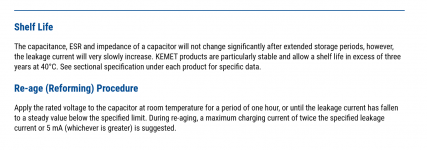
For the record, I am reforming these KMH 10,000uF 63V Nippon capacitors today, following the guideline of the manufacturer - that is, to charge them in 63V through 1k resistor.
I built an LM317 63V regulator on a breadboard, and connected the caps to that output using a 1k, 5W resistor for each one.
They immediately charged up to 60V and 58.9V, and after 5 minutes, they had reached 62.6V. I plan to leave them for 24 hours and then remove them.
If I am correct, the caps seem to be doing very good! Less than 0.4 mA leakage in 5 minutes is encouraging, I think.
Which gives credit to Tony for assuming that these caps did not need reforming at all, but it's the first time I attempt it so I gave it a go.
The caps are indeed less than 4 years old: (codes on post #50)
45aP4M = 27 May 2014
54WP1M= 23 April 2015
These dates conform with this document that can be found online.
Update: 50uA leakage reached in 20 minutes (reached 62.73V while the LM317 output is 62.78V).
Last edited:
This statement on its own is irresponsible and could lead an inattentive cap reformer to blow up the cap with too high voltage.when reforming a 63v cap say, then a voltage source higher, say 100 volts is needed and a 10k 5 watt resistor is added....
This statement on its own is irresponsible and could lead an inattentive cap reformer to blow up the cap with too high voltage.
Yeah, please don't do this unless you have some sort of overvoltage protection. A simple Zener across the cap will suffice, sufficiently rated, of course.
Stupid question, I do have some 22kuF/40V caps that are stocked for something like 10 years now and would like to reform/check before installing them.
I want to use them in a 25V circuit and my lab PSU goes "only" to 35V max.... can I try reforming using the 35V or will that be less efficient than at 40V ?
TIA,
Max
I want to use them in a 25V circuit and my lab PSU goes "only" to 35V max.... can I try reforming using the 35V or will that be less efficient than at 40V ?
TIA,
Max
It will still be better than the 0V they have been standing for 10 years. 
I would not overthink it, simply connect capacitors to available 35V through, say, a 1k or 2k2 resistor and leave that applied for a couple hours or overnight.
Considering that more of testing/checking than real reforming which always seems iffy to me.
Next day disconnect supply, measure charged voltage and then again, say, 15 minutes later.
In my book, if they have not dropped below, say, 30V or so, they will be perfectly fine with 25V nominal rails.
35v is better than 0v but remember reforming with pure DC isn't as good as ding it with half wave DC. In any case the caps are not old enough that your method won't work.I would try doing it for a couple of days but don't be surprised if some of them fail when pressed into service.
urn any equipment in for a few days that you use these reformed caps in to be safe.
urn any equipment in for a few days that you use these reformed caps in to be safe.
This statement on its own is irresponsible and could lead an inattentive cap reformer to blow up the cap with too high voltage.
your opinion.....
100vdc with a 10k ohm in series is just 10mA even with a shorted load, Ohm's laws remember?
i once reformed a 56kufd/63wvdc using similar setup, at 75 volts, the leakage was less than 0.5 mA....
if you are scared that something will blow up, then don't....
Stupid question, I do have some 22kuF/40V caps that are stocked for something like 10 years now and would like to reform/check before installing them.
I want to use them in a 25V circuit and my lab PSU goes "only" to 35V max.... can I try reforming using the 35V or will that be less efficient than at 40V ?
TIA,
Max
if you shorted the terminals of that cap in storage, then there will be no accumulated charge....
i reform caps using a psu that is higher in voltage than the capacitor under testing, the psu has a series resistor of about 10k or more...
for a 40vdc cap i will use a 50v psu, a 10k in series will limit current to 5mA in case of shorts...when the leakage current is less than 1mA, then your cap is reformed...
a defective cap will show leakage current that never decreased with time..
reforming takes time, hours even, when the leakage is way less than 1mA, then you have a reformed cap...
to discharge the cap, i use an incandescent lamp....100 watt/220volt rated...
keep safe...
I check >1 year old caps with a DVM on ohms scale - to 2 volts.
If after that leakage on 20 v scale is < 10 mv per scan, I install them.
Nothing has blown up yet. I've replaced about 400 e-caps since I quit work. Your experience may vary.
Installed some new (from distributor) 100mf and 33 mf @ 35 v caps in last month in organ power supplies. Came with voltage on them. Little leakage, No problem.
Last edited:
Thanks for your input gentlemen, I will cobble something together with a switch and lightbulb for discharge... of course I stocked non-shorted....
They are Rifa caps with a production date code 1 or 2 years prior to storage... so not like finding 50 yrs old caps in a box...
Will keep you all updated!
They are Rifa caps with a production date code 1 or 2 years prior to storage... so not like finding 50 yrs old caps in a box...
Will keep you all updated!
Last edited:
Hi All,
sorry to bother you all again.
But my brain is not prepared for failure mode right now, so I prefer to ask the "dumm" questions that came up....
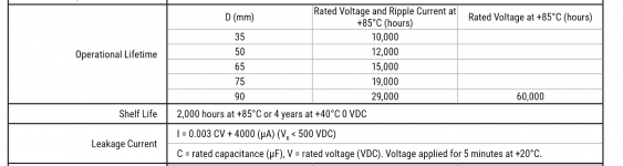
I calculate leakage current as per the formula attached in the datasheet:
I = 0.003 x 22000 (uF) x 40 (V) +4000 (uA) = 6640 uA
The datasheet then suggest to set 5mA or twice the leakage current (around 13mA) if I am not mistaken.
I was thinking of using a 3,3k/6W resistor I have handy and ramping up the voltage from 0 in 10V incremental steps up to 40 to achieve around 12mA.
I am probably overthinking this once more.
I just need someone to say "go ahead" and to get the fire extinguisher closer to the bench.
Thanks to all.
Max
Full datasheet here if needed:
https://www.mouser.fr/datasheet/2/212/KEM_A4034_PEH200-1101128.pdf
sorry to bother you all again.
But my brain is not prepared for failure mode right now, so I prefer to ask the "dumm" questions that came up....
I calculate leakage current as per the formula attached in the datasheet:
I = 0.003 x 22000 (uF) x 40 (V) +4000 (uA) = 6640 uA
The datasheet then suggest to set 5mA or twice the leakage current (around 13mA) if I am not mistaken.
I was thinking of using a 3,3k/6W resistor I have handy and ramping up the voltage from 0 in 10V incremental steps up to 40 to achieve around 12mA.
I am probably overthinking this once more.
I just need someone to say "go ahead" and to get the fire extinguisher closer to the bench.
Thanks to all.
Max
Full datasheet here if needed:
https://www.mouser.fr/datasheet/2/212/KEM_A4034_PEH200-1101128.pdf
Attachments
Last edited:
Result for cap #1 after 3 hours at rated voltage (after incremental 10V steps for 30 min each):
Output of bench: 40.00V
Measure on cap: 39.97V
Voltage drop on 3K3 Ohm resistor: 37mV
Is the leakage current 0.0037V/3300R or 0.03V/3300R ? (See EDIT further down)
It looks "good" enough to my uneducated eyes, but I have a hard time grasping the calculus, I must be mixing something up. I re-read the entire thread a couple of times but still...
Thanks in advance!
EDIT: I had a digit shifted and mistakenly noted 0.0037 for 37mV (whoich is wrong of course) , I 'understand that I measured the same thing with differnent methods, Diff between cap and bench supply, and voltage drop on given resitor.
I understand I do have somewhere between 9uA and 12 uA leakage current depending on how I calculate it ?
I forgot to mention that the resitor is not a precision resistor, and had something like 3267 Ohm or thereabout.
Looks coherent to me over all.
Last edited:
- Status
- This old topic is closed. If you want to reopen this topic, contact a moderator using the "Report Post" button.
- Home
- Design & Build
- Parts
- reforming electrolytic capacitors