Press-n-Peel Blue http://www.techniks.com/
"Temperature setting on the iron is critical, and dependant upon your laser printer or photocopier. Suggested starting temperature is 275-325 degrees F. Iron setting is generally "polyester". Iron temperatures vary. Iron until board has completely and fully reached the temperature of the iron. Time varies with the size and thickness of the board. Generally this is 1.5 to 10 min. "
There don't seem to be any disclaimers about width etc. on the web site. I have laid down and etched .3969 mm traces on 1/2 oz copper bonded to .5 mil polymide film successfully.
Your mileage may vary.
Prosit

It depends where they are in the circuit but I have 10 mils traces which goes under 0805 parts. You can check the layout of QRV07 headphone amp.
http://www.sjostromaudio.com/hifi_files/qrv/qrv07r0layout_cl.pdf
I strive to have 20-30 mils traces and 13 mils as the "normal" thinnest trace but if you are going under a 0805 part you must have 10 mils of if you want to put a trace between SOIC pins, with 50 mils pin grid.
http://www.sjostromaudio.com/hifi_files/qrv/qrv07r0layout_cl.pdf
I strive to have 20-30 mils traces and 13 mils as the "normal" thinnest trace but if you are going under a 0805 part you must have 10 mils of if you want to put a trace between SOIC pins, with 50 mils pin grid.
Originally posted by Bricolo
I wanted to know what was the minimum trace width and spacing I could use with DIY PCBS. The printing is done on a laser printer.
And, what's a good trace width for line level audio use?
Hi Bricolo,
The smaller the traces the more the board will cost (with board houses), with 8 mil traces being reasonable, & 10 mil being better. Traces must be spaced away from other elements & traces, with 8 mil and 10 mil separation being common.
But if your making your own boards you won't want to go below 12 mil traces and spacing, and more would be better.
Current & voltage:
Traces that carry more current need to be wider.
The current handling capacity is proportional to the cross-section area of the trace. So what is the thickness of the copper on the board, 1oz (35uM) or 2 oz (70uM)?
Current handling capacities for a 1 oz. board:
10 mils - 800mA
20 mils - 1.4A
50 mils - 2.5A
Current handling capacities for 2 oz. board:
10 mils - 1.4A
20 mils - 2.2A
50 mils - 4A
Traces with higher voltages need greater separation (spacing) from other traces.
With spacing, the critical factor is the max. voltage difference between conductors. A supply line of 5V & another of 12V has a difference of 7V. Rule of thumb is to allow 0.2mils per volt or 15 mils, whicheve is greater.
There's more to it than this but all of the above can be simplified. For a home made circuit board as wide as possible for both the traces and the spacing.
Hope this helps,
Fred P.
Thank you for the explanation!
I don't know the thickness, I'll ask at the shop newe time.
But is seems that my 40mil setting seems wide enough for line level signals and opamp supply
Traces as wide as possible isn't a problem. But a wide spacing is, because when I increase the spacing the groundplane doesn't go everywhere I want anymore.
Always compromises...
Bricolo said:Thank you for the explanation!
I don't know the thickness, I'll ask at the shop newe time.
But is seems that my 40mil setting seems wide enough for line level signals and opamp supply
Traces as wide as possible isn't a problem. But a wide spacing is, because when I increase the spacing the groundplane doesn't go everywhere I want anymore.
Always compromises...
Rather than use "TRACE 0" (trace zero) as ground plane, I set up a separate powerplane trace -- this goes on the top and bottom then I drill via's through the power planes and connect the two halves at the star ground -- this is a technique from Analog Devices -- I wouldn't recommend it for digital (as you have what would look like a stripline antenna !)
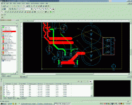
Some programs have the ability to set a shield around a trace -- Ultiboard 7 (which I both love and hate) has this functionality. One of the nice things about Ultiboard is that there is a spreadsheet which you can pull up and easily change trace widths, shields, clearance. See the pic:
Attachments
- Status
- This old topic is closed. If you want to reopen this topic, contact a moderator using the "Report Post" button.
