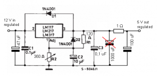
Here's my newest regulator. I changed the resistors to smaller ones to get enough output current and I also changed the 1000 uF Elna Silmic output capacitor to 100 uF Oscon. After very quick listening I would say that sound is a bit lazy now and ambience is not that good anymore. I think its better to burn the components in before making any changes. I'll try to change the 100 uF cap back to 1000 uF and listen if it helps. There's room for both 100 and 1000 uF caps. Should I try to put them both at the same time. I also have 10 uF Oscons it they are better. Opinions are wellcome.
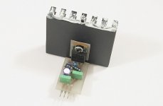
Attachments
Hi there,
this looks nice to me. From the pure technical point of view, it is no difference for the lm317 if you go for a 100 or 1000uF cap. It will run very stable with both.
So we are anow in the "let's experiment" phase. So DIAR, you have to try a little bit with the caps. If you prefer the sound with a 1000 uF, go for it. And try to add 1 nF (Nanofarad) ceramic cap in parallel t othe 1000uF - any audible difference?
And with a 1nF ceramic and a 1 uF cap (liek 1uF WMA FKC, FKP, etc., or Siemens Multilayer cap) in parallel with the 1000uF -- how does this sound?
So we are now in the phase that only your personal hearing (ears & brain) judge about "do the mod" or "do not the mod".
Every combination of caps will neither hurt your DAC, the lm317 or anything else -- so I wish to great expereminetal session - and have some grade 4A finnish beer handy")
this looks nice to me. From the pure technical point of view, it is no difference for the lm317 if you go for a 100 or 1000uF cap. It will run very stable with both.
So we are anow in the "let's experiment" phase. So DIAR, you have to try a little bit with the caps. If you prefer the sound with a 1000 uF, go for it. And try to add 1 nF (Nanofarad) ceramic cap in parallel t othe 1000uF - any audible difference?
And with a 1nF ceramic and a 1 uF cap (liek 1uF WMA FKC, FKP, etc., or Siemens Multilayer cap) in parallel with the 1000uF -- how does this sound?
So we are now in the phase that only your personal hearing (ears & brain) judge about "do the mod" or "do not the mod".
Every combination of caps will neither hurt your DAC, the lm317 or anything else -- so I wish to great expereminetal session - and have some grade 4A finnish beer handy
tekman said:
Every combination of caps will neither hurt your DAC, the lm317 or anything else -- so I wish to great expereminetal session
This is what I wanted to hear
tekman said:
and have some grade 4A finnish beer handy
Yes, dehydration is very dangerous

http://kotiweb.kotiportti.fi/audiovideo/nikkarointi/puhdistus/tarvikkeet.jpg
Diar
I don't know why you change your 7805 for an adjustable 317 which is slightly inferior (if not...the same) to the original. If you think you need a regulator upgrade, at least go for the LM350. You'll be ending out with far better regulators.
Now for your info:
R2 should be changed for 715 ohms for a 4.98V
There should be a temporary 2Kohms resistor for the tests.
If your total capacitance is higher on the output side just put a reversed biased diode from the input to the output. This way, when shutting off, voltage from output side of regulator will be bypassed by the diode instead of destroying your regulator.
Not shown in the spec sheet : R1 should be bypassed with a small 1µF tantalum cap.
If possible use tantalum caps for input and output (C1 and C2).
Good luck
Luke123
Data sheet recommends using 10 uF electrolytic for bypassing R2. I use 10 uF Oscon.
The DVP NS900 manual says that regulator output voltage is 5.2. I set it to 5.1. Voltage level is not as important as how pure it is.
I have both protection diodes as seen on the previous messages.
I have understood that LM317 is much better that LM7805 (when you use preper bypass caps and such).
I'm willing to try better regulators but it is hopeless to try to seach information from DIYAudio. There's just too much of everything.
Has anyone been able to find a good thread about simple CDP regulators (not jung superregulator).
EDIT: Is it ok to replace LM317 with LM350 just like that. I see no reason why this wouldn't be ok.
firework
Hi Luke, when using a tantalum cap for C1 at the input of the regulator it will likely blow up with some firework. Tantalums do not take a large ripple!
Luke123 said:
If possible use tantalum caps for input and output (C1 and C2).
Good luck
Luke123
Hi Luke, when using a tantalum cap for C1 at the input of the regulator it will likely blow up with some firework.
Tantalums do not take a large ripple! Hello Elso
" Hi Luke, when using a tantalum cap for C1 at the input of the regulator it will likely blow up with some firework. Tantalums do not take a large ripple!"
No. The ripple current IS small because there is already some sort of large cap value after the bridge. Anyway 0.1µF is already suggested per the spec sheet. But you're right to state that Tan caps are fragile. Choose one that has at least double or triple the working voltage.
I also forgot to add a 10-100µF across R2.
Luke123
- Status
- This old topic is closed. If you want to reopen this topic, contact a moderator using the "Report Post" button.
- Home
- Design & Build
- Parts
- Overwhelming difficulties with regulators, please help!