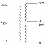
I just bought a transformer for my P101 and the input/output schematics looks a little different than I'm used two. It has dual secondaries and the layout is shown below.
Correct me if I'm wrong but I should connect the primary 0 and 115V connections to AC via fuse and switch. Connect the secondary 0's together or ground and run each of the two 50's into each of the two AC's of the rectifier bridge.
I'm in the US so AC outlets at 115V
Thanks for the help.
Correct me if I'm wrong but I should connect the primary 0 and 115V connections to AC via fuse and switch. Connect the secondary 0's together or ground and run each of the two 50's into each of the two AC's of the rectifier bridge.
I'm in the US so AC outlets at 115V
Thanks for the help.
Attachments
Killjoy99 said:
Correct me if I'm wrong but I should connect the primary 0 and 115V connections to AC via fuse and switch.
Correct!
Connect the secondary 0's together or ground and run each of the two 50's into each of the two AC's of the rectifier bridge.
You must connect one of the secundary 0 to the secundary 50 of the other secundary and ground. The other 0 and other 50 to the AC input of the rectifier bridge.
Regards
Well today I started to work on P39 Soft-start circuit via Rod's PCB. I ordered a 9V Toriodal Transformer to power the relays as seen in the Schematic on his site.
P39 Schematic
I'm not sure how to wire the transformer as it is shown in the schematic. Here is the Datasheet for the transformer. There are 4 leads on the primary which by the data sheet should be paired up for 115V operation.
I'm not sure what to do with the 4 Secondary Leads other than just pair them up. Please help.
Transformer Datasheet
- Status
- This old topic is closed. If you want to reopen this topic, contact a moderator using the "Report Post" button.