Here’s a project for anyone who wants to build an audio taper stepped attenuator volume control on the cheap. Before anyone gets too excited this project is a prime example of “give-and-take” in design. To make it cheap, compromises had to be made. The good news is that it doesn’t compromise on sound quality, so you can try it and see if you like the results before you invest in a much more expensive unit without the compromises. I like to use this design when I’m building a prototype, as I can usually build it for less money than a decent quality stereo potentiometer, and it allows me to optimize the impedance to the circuit I am using it with. I will be slowly posting this over the next few days, so bear with me!
So, you ask, what are the compromises? The primary compromise is made in either the size of the volume change between steps, or the total range from loudest position to quietest. The best stepped attenuators offer between 24 and 30 discreet volume levels. This unit only has 12. The compromise I have settled on is 4.3dB steps between –48dB and –1dB. Others might prefer smaller steps distributed over a narrower range, but for myself I find 4dB steps aren’t too bad. The other compromise is that this is a series attenuator where all the resistors are in the circuit all the time, unlike ladder attenuators or shunt attenuators, which only use two resistors at a time for each channel.
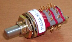
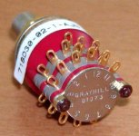
So what do we need? First, a switch! For a stereo unit you need a 2 deck, single pole switch. I like the Grayhill 81073, which as I mentioned earlier, offers 12 switch positions. Lastly, you need resistors in the right order of resistances. For this project, I wanted a 22kohm impedance. The resistor series is as follows, where the position numbers indicate the switch position as seen on the back of the switch.
Position : Value (ohms)
Gnd – 1 : 86.6
1 – 2 : 54.9
2 – 3 : 90.9
3 – 4 : 150
4 – 5 : 243
5 – 6 : 402
6 – 7 : 665
7 – 8 : 1100
8 – 9 : 1780
9 – 10 : 2940
10 – 11 : 4870
11 – 12 : 7870
12 – Input : 1740
So, you ask, what are the compromises? The primary compromise is made in either the size of the volume change between steps, or the total range from loudest position to quietest. The best stepped attenuators offer between 24 and 30 discreet volume levels. This unit only has 12. The compromise I have settled on is 4.3dB steps between –48dB and –1dB. Others might prefer smaller steps distributed over a narrower range, but for myself I find 4dB steps aren’t too bad. The other compromise is that this is a series attenuator where all the resistors are in the circuit all the time, unlike ladder attenuators or shunt attenuators, which only use two resistors at a time for each channel.
So what do we need? First, a switch! For a stereo unit you need a 2 deck, single pole switch. I like the Grayhill 81073, which as I mentioned earlier, offers 12 switch positions. Lastly, you need resistors in the right order of resistances. For this project, I wanted a 22kohm impedance. The resistor series is as follows, where the position numbers indicate the switch position as seen on the back of the switch.
Position : Value (ohms)
Gnd – 1 : 86.6
1 – 2 : 54.9
2 – 3 : 90.9
3 – 4 : 150
4 – 5 : 243
5 – 6 : 402
6 – 7 : 665
7 – 8 : 1100
8 – 9 : 1780
9 – 10 : 2940
10 – 11 : 4870
11 – 12 : 7870
12 – Input : 1740
Attachments

Interesting.. But How Cheep?
'Bottlehead' sells a Dual Mono Kit switches (12 position,11 useable steps) and an assortment of Resistors .. with instructions for.. linear or log steps. for $40.
Granted ithe switches are plastic and not overly robust .. but they work surprisingly well in actuall use.
Would like more substantial switches..
Any linfo on the where and how much for the Greyhill switches.. for a vancouverite ??
I don't have the exact prices of the top of my head, but I ordered everything from digikey, enough for two complete stereo attenuators, and I think it was around $50CDN including taxes and shipping.
The Greyhill switches I'm using are plastic and metal, but they are quite robust, and have a very positive feel when being switched. You can turn the shaft reasonably easy just with your fingers on the shaft too.
The Greyhill switches I'm using are plastic and metal, but they are quite robust, and have a very positive feel when being switched. You can turn the shaft reasonably easy just with your fingers on the shaft too.
I have no idea if they are non-shorting or not, but so far I haven't found anything objectionable about their performance whatsoever. No clicks or pops on switching, smooth switching action with a very positive stop at each position. I have a Goldpoint series attenuator and with the exception of the greater number of steps I don't find any noticeable operational or audio difference. A nice note is that the same switch is also available in a 4-deck configuration which would be ideal for a stereo attenuator for a balanced circuit.
A nice note is that the same switch is also available in a 4-deck configuration which would be ideal for a stereo attenuator for a balanced circuit.
You only need two decks for balanced stereo. I think Peter Daniel was the first to post the circuit here (attenuator as shunt between inverted and non-inverted lines, after series resistors). Obviously all series/parallel resistances around this circuit need to be taken into account. I'm using that configuration to great success with Ro(e)derstein MK3 resistors, although resistances needed to get a proper dB attenuation sequence have to be recalculated, as the usual log curves do not give a good result if you do that. The only problem with this setup is that if a non-shorting switch is used (as in my case), the breaks between positions will result in maximum volume. I use an IR sensor that acivates the muting relays on in-between positions (and makes sure the motor doesn't stop the switch on an in-between position), so I get a momentary silence between switches, but it's not a problem for me. Shorting switches are harder to find at low prices, so this is an option.
Hmm.. Mebe the Bottlehead switches ARE good.
these are shorting switches. set up inna Shunt mode..absolutely no pops/noises between positions.
Switches ARE plastic cased tho and this led me to doubt their ultimate quality, perhaps unfairly, but they DO work beyond expectation and the instructions are pretty well Fool proof for a variety of configurations, including as a 'Passive'
I'm now thinking that I won't be trying to 'improve on 'em untill they actually give a problem.
OK, I had a brief hiatus while dealing with other issues, sorry for the delay. So to continue:
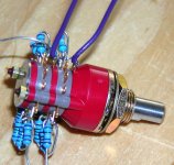
Start by soldering the resistors between the switch positions. I.e. the 1-2 resistor I previously indicated will bridge the terminals for switch position 1 and 2. Out of habit I start with the ground – 1 resistor and add along towards the 12 terminal.
Start by soldering the resistors between the switch positions. I.e. the 1-2 resistor I previously indicated will bridge the terminals for switch position 1 and 2. Out of habit I start with the ground – 1 resistor and add along towards the 12 terminal.
Attachments
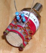
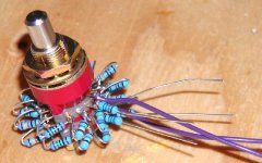
Before I reach the terminals for switch position 12, I add the output wires to the terminals for the switch connection.. Yes, I know the terminology I’m using is a little confusing, but the pictures should explain it clearly. Send me an e-mail if it doesn’t make sense.
Attachments
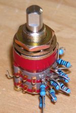
Once all the resistors are soldered on, the only thing left is to make the input and ground connections. Ground connects to the free end of the resistor soldered to the 1 terminals. Signal input connects to the free end of the resistor soldered to the 12 terminals.
Attachments
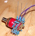
Another view of the finished attentuator without the input and ground connections.
I should have mentioned that the reason I solder the output wires before completing the resistors is because the output terminals are damn hard to get at with a soldering iron once all the resistors are added.
I should have mentioned that the reason I solder the output wires before completing the resistors is because the output terminals are damn hard to get at with a soldering iron once all the resistors are added.
Attachments
I know I promised the spreadsheet for determining the resistor values, but I need to make a little more user-proof before I post it. I'll try to get that edited in the near future and posted. It isn't particularly intuitive as it currently stands (except to me), so bear with me as I tidy it up.
Terry
Terry
My attenuator is shunting between balanced lines, so only two decks for stereo. To get a proper attenuation curve, calculating the values is different than in other setups. The goal is to get a curve like the one Goldpoint uses (mostly 2 dB steps except at the extremes). Here's the spreadsheet (attached) I used to get resistor values, along with the closest Roederstein MK3 values available (marked with the prime ' symbol). Others can use this by changing the formulas for their own particular setup - take into account all parallel and series resistances (needless to say you can't just use it without modifying it; I had something like 1K in series on each line before the attenuator shunting in between, 300 in a filter before it, and 511K to ground on each one after some DC blocking caps, so that's where my numbers come from).
Attachments
And here's a photo of my MOTORIZED attenuator (since I'm using a remote control). Input comes either from the front plate or the remote control. The knob doesn't turn, just a bit to activate switches. Indication of volume is done with a little arrow you can see behind the knob, attached to the driving motor by a cylinder coaxial to the knob axis and then the rope (the rope is tentioned by an elastic). The motor has a lot of reduction gears and is driven by a MOSFET H-bridge, so that it can get good torque. The attenuator itself is in the DAC sub-enclosure for shielding. The toothed cardboard attached to the attenuator is for the IR sensors which, using logic, prevent the motor from stopping at an inbetween position. Microswitches prevent forcing the attenuator beyond the stops.
An externally hosted image should be here but it was not working when we last tested it.
- Status
- This old topic is closed. If you want to reopen this topic, contact a moderator using the "Report Post" button.
- Home
- Design & Build
- Parts
- Cheap Stepped Attenuator Project