Hello all, so what I'm needing to build is a simple way to drive around 500 LEDS in sequence. About 100 steps in 5 channels. I was thinking of using a simple RC network to turn on the gate of a transistor after a determined amount of time and just building a few hundred of those- each increasing in delay time, but would that work? Is there another simple way? I was also thinking of using the standard 555 driving decade counters cascaded. This does not have to be a precision thing, it's a one shot deal. Ideas? Thanks!")
Led Bargraph
There are many diagrams around for LED bargraphs using comparitors. 10 step ones. You just need to take one of those, and put in a whole lot more comparitors and divide the voltage steps a lot more finely in the reference ladder.
I hope someone is paying you well for this.
There are many diagrams around for LED bargraphs using comparitors. 10 step ones. You just need to take one of those, and put in a whole lot more comparitors and divide the voltage steps a lot more finely in the reference ladder.
I hope someone is paying you well for this.
Thanks Dan, that's what I think I'm going with. There is a schematic for a circuit using 5 3914's cascaded in a new thread for it named "Help with this schematic?", but I'm not sure if it will work as I have not used them in bargraph mode cascaded. This is for a brother, so no, no money exchanged.
500 LED or 50 LEDs?
Even a 50 step LED meter is finer a resolution than you can possibly use. The lights jump around too much for any more than 20 to be useful. Actually, if you ised a single LM2914 but put 2 LEDs on each step he would not likely know the difference.
That is, you are building an audio meter? Then the LM3916 is the one to use. The LM3914 is for a linear meter.
If he needs more than 20 or 30 steps, and the reading is steady enough to use then mayby a digital panel meter would be better.
Really think if you need this much resolution on a freebieproject. At least get you brother to mount all the LEDs and wire them up.
If you're just after an up-down column of lights with stacked LM3914's, a 0-10V signal will easily light 100 leds.
The most basic circuit is a 1.25V range, but it's easy to adjust for higher or lower sensitivity by tapping off the internal regulator. Check the datasheet, it's well covered.
The most basic circuit is a 1.25V range, but it's easy to adjust for higher or lower sensitivity by tapping off the internal regulator. Check the datasheet, it's well covered.
While the 3914 is a nice compact way to drive 10 Led's, I get the impression (from your initial suggestion of an R-C timer circuit) all you need is a sequential string of LED's that light up, not an actual LED meter or anything fancy. You also mentioned "5 channels" which I assume means you need each step to light 5 LED's at once. That may be more current than the 3914 can handle.
Another approach would be to use SCR's. You can get "sensitive gate" SCR's fairly cheap, and trigger them using the series resistor and parallel capacitor idea you talked about. You wire it so once one SCR turns on, it's output not only lights the next step of LED's but provides the source for the next SCR's gate, through another resistor/cap delay of course. And since SCR's lock ON once triggered, they will stay lit until you drop power.
The advantage of SCR's is they will handle much more current than the 3914. The disadvantage is they are discrete devices (more wiring) and you are limited to the "turn on" sequence, they won't "back down" like the 3914 will.
It's just another option. Here's a cheap source for SCR's that would work. They're 10/$1 and handle 800ma, with the sensitive gate you'd want for such a circuit. http://sales.goldmine-elec.com/prodinfo.asp?prodid=6622
modifry, that's a really good idea, I wouldn't have thought of it. I won't be doing the construction, so in theory I can make it all discrete if I want. However the 3914's would be a fraction of the parts count. I'm looking at 50 steps X 5 with one led on each output, so 250 leds driven by 5 sets of 5 3914's, each with independant input signals. It's gonna come down to cost (as always) so I'm gonna plot out each idea and see what's most economical. Thanks!
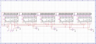
However the 3914's would be a fraction of the parts count. I'm looking at 50 steps X 5 with one led on each output, so 250 leds driven by 5 sets of 5 3914's, each with independant input signals. It's gonna come down to cost (as always) so I'm gonna plot out each idea and see what's most economical. Thanks!cpemma, the datasheet is what I used to build this schematic, but is this the correct way to cascade them? The data sheet only touches on using these cascaded in bar graph mode unfortunately. Oh, and just fyi, this is for an effect of vains of light shooting up a tree from botton to top for a musical production. It's for my bro who is a lighting designer. The leds don't have to cycle back down- just up so modifrys scr idea would work fine but the 3914's do have a much lower parts count. Thanks!
Attachments
For bar mode only, I'd think a raft of quad opamps (LM324) or comparators (LM339) would work out far cheaper than using several LM3914 chips.
You could run the chips off say 18V and chop say a regulated 15V up with a resistor chain to use as the references for each level. A pot on the supply gives you the comparison voltage.
You could run the chips off say 18V and chop say a regulated 15V up with a resistor chain to use as the references for each level. A pot on the supply gives you the comparison voltage.
sequential LED in DOT mode
If you are not interested in voltage and only interested in DOT mode, then you should use 4017s in a tricky way.
This was the need in one timer and I wanted to indicate the step number by a glowing LED. The oscillator was made programmable using ICM7217. This is something like a programmable mechanical street light timer.
The trick...
Follow carefully
LED 9(at pin 11) is not connected in all 4017s
The pin 11 is utilised to disable the present chip though an EX-OR gate and enables the next through another EX-OR. One input of the first EX-OR ic is tied high(can be looped also).The EX-OR output goes to clock inhibit (pin 13).
tie all resets together and all clock pins together. Get your clock and reset with large fan-out
Pin 11 will go to one i/p of self EX-OR and one i/p of next EX-OR
You want them to come back and forth, then place the LEDs wherever you want.
LED No.1-No.50-2-49-3-48-4-...
Gajanan
Hi gmphadte, i see you've found the other thread.
To Moderators: I didn't mean to start two threads on the same subject- my appologies.
cpemma, that's another great idea. Would a LM324 or something similar be ok with outputting dc? Would it be stable driving a load such as an led? I've never used one for anything other than audio. The 3914's are under $2 each and they include everything I'd need to have a working display, but the op amp idea is interesting- might be easier to configure for custom trigger levels. Hmmm.
another ic
You have to use LM339, a quad comparator with open collector. Typical output sink current is 16 mA.
Connecting a currenr source instead of resistors for LEDs will save lot of wiring trouble. Connect a ladder made from LEDs to the outputs, below the cc source. Being open collector the output transistor that conducts will prevent others from lighting.
Vcc--16 mA CC source--LED1 A - LED1 K--*--LED2 A - LED2 K--*--LED.....
Use higher Vcc to make a longer chain
K-cathode
A-anode
* Comparator o/p goes here
Ground is not connected
Gajanan
It can be connected as a comparator, no feedback resistor, just the reference voltage to one input, voltage signal to the other. Output swings from 0V to (Vs-1.5) on a single rail supply, IIRC will source 20mA OK. See the datasheet to check.imix500 said:Would a LM324 or something similar be ok with outputting dc?
- Status
- This old topic is closed. If you want to reopen this topic, contact a moderator using the "Report Post" button.
- Home
- Design & Build
- Parts
- Sequential LED driver.