how does one tell the power ratings of a resistor i need bleeders for the filter capacitors of a power supply...i have millions of resistors but for the life of me cant figure out the power ratings...is there a way u can see it on the body of the resistor...i have a few where there are no colour bands on thye resistor where the resistance and the power rating is written on the body....but they are not what i need...is there a way to tell the ratin
Hi alecwek
I was writing an attempt to explain but I found this:
http://www.tpub.com/neets/book1/chapter3/1-8.htm
Couldn't do any better")
/Hugo
I was writing an attempt to explain but I found this:
http://www.tpub.com/neets/book1/chapter3/1-8.htm
Couldn't do any better
/Hugo
umm..i kinda know what power is.....
so baically a 10 watt resistor would be the size of a coke can,....
ok then how about this....i ve got 2200uf capacitors that i need to dicharge when the amp is turned of their max rating 50volts.....does the resistance really matter.....1round 5k is ok right....but what power rating should they be....
though,thanks ...netlist
If you know what current will go trough that bleeder you can calculate the power dissipation. Double that value for safety margins and there you are. Something like 5W me thinks.
It could be the size of a small coke can though
No serious, a 5W resistor is only about 2cm or a small inch long.
Google for a picture.
/Hugo
It could be the size of a small coke can though
No serious, a 5W resistor is only about 2cm or a small inch long.
Google for a picture.
/Hugo
Assuming the bleed resistors are always in circuit and I guess we are talking PSU reservoir caps, you won't want too much current flowing through them.
1mA is a good value, so 47kΩ sounds about right. This only needs to be 1/4W.
OK, so you reckon 10mA bleed is OK, then a 4k7 will do and it'll be 1W.
Which you choose determines how long you want to wait for the volt to die away
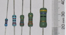
For your average colour band type, power rating isn't stated, you "just know" by looking at their physical size.
To help, here's a piccie of some different ratings.
From left to right:-
1/4W metal film, 1/2W metal film, 1W, 2W, 3W carbon film.
Hope this helps
1mA is a good value, so 47kΩ sounds about right. This only needs to be 1/4W.
OK, so you reckon 10mA bleed is OK, then a 4k7 will do and it'll be 1W.
Which you choose determines how long you want to wait for the volt to die away
That's a very good question.how does one tell the power ratings of a resistor
For your average colour band type, power rating isn't stated, you "just know" by looking at their physical size.
To help, here's a piccie of some different ratings.
From left to right:-
1/4W metal film, 1/2W metal film, 1W, 2W, 3W carbon film.
Hope this helps
Attachments
YOU KNOW....WHEN I FIRST POSted...sorry...anyway...i thought the answer would be in the colour of the resistors because i noticed that most of my big resistors..in size not ohms....were green the other smaller ones were blue or red or...well i was hoping there was a sure fire way of telling....guess that would make life to easy ....AND WE JUST CANT HAVE THAT CAN WE
thanks anyway...ill print out the image...be quite handy to have around when im looking for a certain resistor...thanks....
....AND WE JUST CANT HAVE THAT CAN WE thanks anyway...ill print out the image...be quite handy to have around when im looking for a certain resistor...thanks....
Everything in electronics is Ohms Law. If it's not Ohm it's Hype.alecwek said:....i ve got 2200uf capacitors that i need to dicharge when the amp is turned of their max rating 50volts.....does the resistance really matter.....1round 5k is ok right....but what power rating should they be....
50V, 5k, so W=V*V/R = 0.5W
Everything in electronics is Ohms Law. If it's not Ohm it's Hype.
Very true.
Agreed, actual power requirement is 1/2W (ish), and adding a safety factor, that means 1W if metal film and 0.66W if carbon film.
I.e. know your actual power dissipation and always overrate so the device lasts for years.
THE SAGA CONTINUES
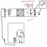
ok all those self problaimed experts here is one for you.....there is a schematic linked of what im talking about....i had a transformer....about37Vac linked to a full wavbridge that leed to 2200uf capacitors rated at 50v...ok and 5k draining the caps....so when i turned the whole thing on ...the ground to positive rail measured 14volts dc...then 13.9...then 13.8.........when it finally got down to around 10volts dc the damn caps blew up.....lucky for me i had baracaded myself behind a shelf......(to get to the switch...hmmmm thank u lord...) anyway pop!!!and suddenly the caps went to cap heaven.....why....why did they have to leave me??????????
i got a little carried away with the schematic...sorry....
Attachments
Sorry to complicate things....
An important consideration is temperature de-rating.
What this means is that the 1 watt resistor you chose to dissipate 600mW, won't be adequate if the ambient temperature is raised. Most de-rating can be accommodated by just choosing a resistor of double the rating. However, in a really warm environment - near other heat generating components, or in an enclosed space, you have to consult the manufacturers' data. They will usually publish a simple graph of dissapation vs temperature.
Nice schematic
Caps go bang when the leakage current through them is too high. That will happen if the polarity is reversed, or if their voltage rating is exceeded.
Don't forget that the DC across those caps will be nearly 1.5 x the AC into the rectifier. Also the AC voltage may be 20% higher than specified with no load current being taken.
I'll pray for your caps...
dhaen,
You beat me to it .. I couldn't get at diyAudio .. it just timed out
The caps almost certainly were connected reverse polarity.
The sequence of events, time line, and the consequence says this is most likely.
I can hear the bubbles forming
That is one of the best circuit diagrams ever, alecwek !
Assuming it's to scale, I calculate the BANG to be 108.43dB spl at 1 metre
Ohm's law?6SN7GT said:
Assuming it's to scale, I calculate the BANG to be 108.43dB spl at 1 metre
Love the drawing, be careful though!
/Hugo
A 50Kohm/20 Watt Vitreous Dale resistor is about 1.5 inches long, .6 inches in diameter, the sand cast power resistors are a little smaller.
Bleeders -- you should figure that the value of the bleeder resistor will reduce the voltage on the capacitors by about 90% in the time it takes you to remove the amplifier cover -- 30 seconds -- the equation is: V(f) = V(i) * e^(-t/RC).
where Vi is the initial voltage and Vf the final voltage --
let's say you are using 470uF of filtration on 400 VDC -- a 27K ohm resistor will bleed the caps by 90% in 30 seconds or thereabouts.
the current drawn by the bleeder is 400V / 27000 Ohms = 14.8 ma. The power is thus (.0148^2) * 27000 = 6 watts. A 10 Watt resistor will accomodate a big swing in the supply voltage. this is a lot of power to burn, however.
ok... now that u mention it...the caps were connected in revers.....man!!!its cause when i kept flipping the breadboard round ...up down....alittle to the left!!!...i guess i must have gotten the rails the wrong way round........i drew schematics on the non copper side before soldering so i had to keep flipping to solder.....man i gotta learn how to make pcb.....also u should see how crap my finished peices look...hmm...ah well.....
what is the best looking.....quickest.....(cheapest )way of making curcuits....pcb look a bit expensive and complicated....plus how on earth do you sheild pcb lines..........
now that u mention it...the caps were connected in revers.....man!!!its cause when i kept flipping the breadboard round ...up down....alittle to the left!!!...i guess i must have gotten the rails the wrong way round........i drew schematics on the non copper side before soldering so i had to keep flipping to solder.....man i gotta learn how to make pcb.....also u should see how crap my finished peices look...hmm...ah well.....what is the best looking.....quickest.....(cheapest
)way of making curcuits....pcb look a bit expensive and complicated....plus how on earth do you sheild pcb lines..........Ah ha!, I think we got to the bottom of the exploding caps problem OK.
So that's good.
I agree, you have to be careful with breadboard designs and remember which side you are working from.
Why do you want to shield PCB lines ?
Because the interconnect wiring is effectively 2D, crosstalk (interference) can be managed reasonably well.
You have something in mind I guess ? Do tell.
well its just cause i heard,....from one of the thousands sources (that are found in great abundance in electronics)
that high voltage lines should be sheilded ...and also high voltage points...caps..etc...i guess cause of noise, also i could imagine it being ......ummm.....healthier, to keep power rails and high voltage ,current lines sheilded...less chances of accident...but man, electronics is polluted with so much good advice its hard to get a grip on it all....
that high voltage lines should be sheilded ...and also high voltage points...caps..etc...i guess cause of noise, also i could imagine it being ......ummm.....healthier, to keep power rails and high voltage ,current lines sheilded...less chances of accident...but man, electronics is polluted with so much good advice its hard to get a grip on it all....
- Status
- This old topic is closed. If you want to reopen this topic, contact a moderator using the "Report Post" button.
- Home
- Design & Build
- Parts
- power ratings of resistors