Balanced stereo step attenuator ladder type question!
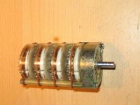
How do I figure out which values of resistors to use in a balanced stereo step attenuator. One friend gave me two very nice ITT 4-pole switches, and I'm planning to use it for my Aleph P 1.7 project.
I found few scripts on the internet that are calculating ladder type configuration for unbalanced mode. But I would like to use both, balanced and unbalaced. So I need 8 decks. Can I use same value of resistors for both + and - balanced, as I use for unbalanced?
So, lets say I want 39dB attenuation. For unbalanced ladder I have to use 99878 ohms for the input (Rx) and 708 ohms for the ground (Ry). Can I use same value of resistors for input of + and - balanced and just use the same ground resistor?
Attachments
If you want to do it balanced, you can use just 3 resistors: 2 resistors from the two source phases, and at the end one resistor connecting them. The ends of this resistor goes to the two inputs. This last resistor is the one you switch. You really need only a single switch deck for it.
Jan Didden
Jan Didden
Check out figure 2 of this page:
Balanced attenuator
Such an arrangement with a fixed input resistor may give problems in a passive preamp because of the variable output resistance, so best to use short cable to power amp.
Balanced attenuator
Such an arrangement with a fixed input resistor may give problems in a passive preamp because of the variable output resistance, so best to use short cable to power amp.
janneman said:Yes that's what I meant.
Jan Didden
Is it possible to have absolute zero volume with this?
dioklecijan said:
Is it possible to have absolute zero volume with this?
Yes. Zero ohms between the legs. Come on, you don't need ME to tell you that!
Jan Didden
Note that doing this kind of balanced volume control changes the calculation for the resistances you need to get a given attenuation.
Here's a standard dB step sequence as used in the Goldpoint controls.
http://www.goldpt.com/taper.gif
Here's my calculation, with disclaimer that I haven't doublechecked it:
Let each series resistor be S ohms and shunt resistors be H ohms.
Output voltage is input voltage times H/(H+2*S).
In dB, attenuation A=20*log_10(H/(H+2*S)).
Solving for H, for a given attenuation the shunt resistor H=(-2*S*10^(A/20))/(10^(A/20)-1), where '^' indicates exponentiation.
If there are any other resistances in series or parallel with this circuit they need to be considered in the calculation.
To get 0 dB H is infinite, i.e. no resistor; a short of 0 ohms for H will not completely eliminate sound because it's unlikely the non-inverted and inverted lines are exactly identical.
Thanks for your comments guys. I'm starting to understand it. But I want to make it for balanced and unbalanced mode. Can I just use this schematics for my attenuator? Left side for the unbalanced, + and - balanced, and right side for the ground as it says on the pic.
Attachments
Prune said:Note that doing this kind of balanced volume control changes the calculation for the resistances you need to get a given attenuation.
Here's a standard dB step sequence as used in the Goldpoint controls.
http://www.goldpt.com/taper.gif
Here's my calculation, with disclaimer that I haven't doublechecked it:
Let each series resistor be S ohms and shunt resistors be H ohms.
Output voltage is input voltage times H/(H+2*S).
In dB, attenuation A=20*log_10(H/(H+2*S)).
Solving for H, for a given attenuation the shunt resistor H=(-2*S*10^(A/20))/(10^(A/20)-1), where '^' indicates exponentiation.
If there are any other resistances in series or parallel with this circuit they need to be considered in the calculation.
To get 0 dB H is infinite, i.e. no resistor; a short of 0 ohms for H will not completely eliminate sound because it's unlikely the non-inverted and inverted lines are exactly identical.
I agree. You can use any 'normal' unbalanced calculation if you realise that at the end you have to split the series resistor in two equal parts of half the calculated value for each leg.
Edit: removed cm nonsense
Jan Didden
- Status
- This old topic is closed. If you want to reopen this topic, contact a moderator using the "Report Post" button.
- Home
- Design & Build
- Parts
- Blanced stereo step attenuator ladder type question!