Hi, I'm working on a preamp for my computer and have come up with the following. The first section is based on an ESP project so I know that should be good. I then try to bridge the 2 channels and pass the bridged info onto a LT. I used the spreadsheet to get the values of the LT so they should be right, I just want to verify the shematic will work before I try making a PCB.
Thanks!
Thanks!
Attachments
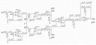
Exactly UrSv, I am making a decent quality computer preamp. I want use the preamp to drive the LT and also output to a stereo amp for full range and a powered sub I am making through the LT. I thought by including LT in the preamp I wouldn't have to mess with a plate amp I already have, and wouldn't need an external box and powersupply to run the LT.
I don't need source selection since it will only be used for a computer system, just a fancy volume control.
I don't need source selection since it will only be used for a computer system, just a fancy volume control.
Firstly I am by no means a professional, and even calling me an amateur on the subject is probably more credit then I should get. But I’m not clear on what some of these op-amps are doing, and it seems like they could be removed.
The first set seems superfluous since your computer has an op-amp too and you should be getting enough signal to make the volume pots work. Then after you combine channels, why not just go right into the LT?
It would certainly help simplify the circuit anyways..
The first set seems superfluous since your computer has an op-amp too and you should be getting enough signal to make the volume pots work. Then after you combine channels, why not just go right into the LT?
It would certainly help simplify the circuit anyways..
Ok, it looks like the schematic will work so I'll work on the pcb. I'm trying to make it universal, so in the future if I like it, I can make it into an audio preamp.
How would the rest of you bridge the 2 channels. This is just a way I have seen it done before. Also, I picked a TL072 since it's only a low frequency curcuit. I also have OPA2134's, OPA2604's, NE5532's, etc.
Thanks for the help!
How would the rest of you bridge the 2 channels. This is just a way I have seen it done before. Also, I picked a TL072 since it's only a low frequency curcuit. I also have OPA2134's, OPA2604's, NE5532's, etc.
Thanks for the help!
Hi -
One thing I notice is that each pre-amp output has a resistor to Gnd.. As these pre-amps are being summed into a virtual Gnd anyway, these pull-downs are not needed.
My advise would be to make the summing resistors equal to the required loading, and set the feedback resistor to give the required gain.
The AC transfer (frequency response) from the pre-amps will (in the present circuit) be determined by C10 || C11 and R26 || R1 - If you have not calculated for the fact that R1 is loading C10||C11 then you will lose LF response.
If you require C10||C11 into 100k, remove R26, and change R1 R2 + R3 to 100k - and do the same for other channel (remove R31).
I wouldnt mind a copy of the gerbers if you do a PCB for this - would be quite a useful board!
Fred.
looking again at the circuit, I dont like what I just suggested! - The problem is that the L and R outputs also become possible (noise) inputs to the summing amplifier... Worse than this, any DC on these outputs would be coupled directly to the input of the summing amp.
I would leave the pull-down resistors (R31 and R26) and connect R1 and R2 via another pair of capacitors directly to the outputs of the op-amps. You could make R1,R2,R3 = 470k, and reduce the additional capacitors to about 470n(total) for the same frequency response.
Again, the response of the L and R outputs will be determined by total loading - but at least any signal injected into these outputs will face attenuation by the C's R's and output impedence of the opamp.

- Status
- This old topic is closed. If you want to reopen this topic, contact a moderator using the "Report Post" button.
- Home
- Design & Build
- Parts
- Can you take a look at this schematic?