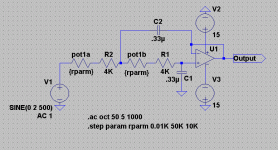
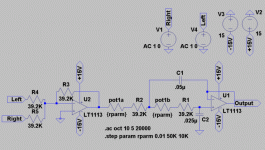
What do you all think of this? I’ve had an impossible time trying to find an easy adjustable crossover circuit for my sub amp project.
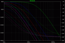
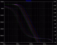
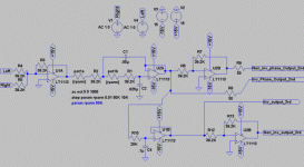
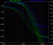
Pot1a/b is a 50K stereo pot. The model shows this pot in steps of 10K, The aprox 120hz crossover area (green line) is the pot at zero resistance. The 50K position is a crossover region around 9hz (gray line). I’m using a 50K pot because it is what I have on hand, I may adjust this to a 5 or 10K pot to yield a low crossover point of 50hz or 35hz respectively.
The shown circuit will be followed by an inverted TL072 with no gain and a switch to bypass that (phase invert switch) and a pot on the output of that for general volume control. All that followed by 2 paralleled lm3875 or 3886 at 31V DC into a parallel coil 3.5 ohm Shiva (it’s a prototype shorted voice coil Shiva, so it may have a bit lower resistance then the typical)
Attachments
Updated calculations
No one has offered any help or suggestions yet, and I’m not surprised. This is either a subject no one really cares about, or something that most have decided isn’t worth the trouble.
As a service to others who search for this in the future I will try and document my progress here. So anyone who can offer any help, please do, and with that I’ll get started.
I found that my general guessing using the calculator found in WinISD and then modeling things in LTspice (free download) left quite a bit lacking, namely a proper 2nd order curve, and my –3db (corner frequency)calculations.
After finding that a Sallen-Key type filter was the easiest to implement both in number of parts and simplicity. And after doing some searching to find the equasions for calculating for a Sallen-Key crossover, I found
This page at t-linespeakers.org. It has the calculations for picking a capacitor and resistor values based on wanted crossover frequencies.
For this project I am only concerned with a unity gain adjustable low pass crossover. For this type of circuit you need to calculate for a second smaller value capacitor, and then for a series resistor to be used in conjunction with a potentiometer of a certain calculated value. The calculations that can more or less be pasted into a spreadsheet program are.
Calculation for second cap
="wanted value of first cap" /(4*(SQRT(2)/2)^2)
Calculation for resistance at LOW freq
=1/(2*PI()*"required low freq"*(SQRT(("value of first cap in uf"*0.000001)*("value of second cap in uF"*0.000001))))
Calculation for resistance at HIGH freq
=1/(2*PI()*"required high freq"*(SQRT(("value of first cap in uf"*0.000001)*("value of second cap in uF"*0.000001))))
You use the value of the lower resistance resistor (the resistor for the higher freq) in series with the pot, and the difference between the resistor values will be the value of the pot.
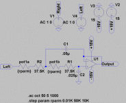
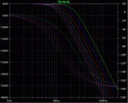
An example of how mine worked out, I used an initial value for a capacitor C1 of 0.05uF, and this gave a value of 0.025uF (25nf, or 25000pF) for C2. My low frequency is 50hz, and this gives me a required resistance of 90K, and my high frequency is 120hz, this gives me a resistance of 37.5K. So R1 and R2 will be 37.5K and 90K-37.5K=52.5K or about a 50K pot. (The use of a 50K pot will change the low cutoff frequency from 50hz, to 51.4hz, but that’s close enough for the women I go with). Also note that I could not find any 0.025uf capacitors, you could use 2 0.025uf in series, or a 0.022uf or 0.027uf should be close enough too.
What your left with should look something much like what I’ve posted below (if you use all my same numbers). Values can be adjusted for capacitors or pots on hand. Generally speaking a larger cap will require a smaller value pot.
Next up is summing a left and right channel, as well as accepting speaker level inputs and adding some gain so we have something to attenuate later. Then a phase switch, since this is a second order crossover we’ll defiantly need one of those.
Attachments
OK, so today we’ll go over summing a left and right channel for those that don’t have a sub out on whatever they are hooking this up to. But first there are a few small problems and oddities with yesterdays design.
1) The capacitor values of C2 are hard to find, and they can be adjusted a bit in either direction, although this does change the crossover slope it is very minor. I’ll just be using two 0.05uf capacitor’s in a row to get my 0.025uf.
2) The resistors R1 and R2 are also of a not very common value, since this really will only change the Freq High crossover point, it is also a minor issue. R1&2 values between 37K and 40K should be attainable and will leave the Freq High point somewhere between 122hz, and 112hz (respectively). I’ll be using 39.2K from here out, giving me a high freq point of 114-115hz.
3) As for connection of the pot, only use the center leg and one outer leg to adjust resistance do not connect the leftover leg to ground or do any other stuff like that.
Now on to new things!
(well new to me anyways)

ver 0.3 Left&Right sum, and Invert
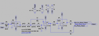
R4 and R5 are the resistors used to set input impedance and to isolate the channels from each other. The value 39.2K was used as it’s the same as we are using elsewhere, and the less different parts we have floating around that happier I am. R3 sets the gain of this op amp at 6db (2x). Larger R3 values could be used to get more gain (if R3 was 392K you would have a gain of 10 (26db)). I don’t know if we need it or not. And I probably won’t know unless someone chips in here. Chances are I will leave this section of my circuit with some space, so that I can serial a few more of these 39.2K resistors to adjust the gain).
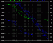
This is also an inverted Op-amp and it will give us a nice inverted phase at the output as you can see in the lower output graph.
Attachments
Ver 0.4 phase switch
Next step is easy as pie too, add an inverting op-amp, with no gain and have a switch Leading to the output. After the switch, you can add a pot for overall gain control I’d say you would be ok with pretty much any value from 5K-50K and then from that right into the power Amp section of the plate amp.
I’ve set R6 and R7 at 39.2K just because it seemed easy, and since if your using metal film resistors from digikey you will have to get 10 of em anyway. R8 and R9 are 50omh resistors and they may not be needed. It just seemed like a good idea to include them when I was putting this together and I’ve just left em. When I build I think I’ll try leaving them out at first.
Attachments
No replys
I think you have no replys because this is all circuitry that was worked out by 1975 and holds no mysteries to anyone with over 5 years experience in circuit design. You have here, basically, the crossover circuitry for almost every computer speaker system that has a sub woofer.
Yes, you have to use capacitors in a 2:1 ratio if you want a decently sharp curve. Do build it. It will work fine.
Thanks for the reply, It didn't seem like it was something very difficult, especially after putting this model together. 
But I was unable to find very much info either here, or with google on designing this type of a circuit. Maybe I just had a poor choice of words, or didn't dig deep enough.
Anyway, I’ve got everything ordered up, and hopefully this will help the next newbie who wanders past looking to do the same thing.
Best part was everything from mouser was only like $6

But I was unable to find very much info either here, or with google on designing this type of a circuit. Maybe I just had a poor choice of words, or didn't dig deep enough.

Anyway, I’ve got everything ordered up, and hopefully this will help the next newbie who wanders past looking to do the same thing.
Best part was everything from mouser was only like $6
While waiting for my parts to all come, and analyzing the crossover curves, and reading some more about them, and seeing how some didn't like the idea of a 2nd order crossover as it didn't fall away quick enough, And since i had some time. I've added to the circuit a bit. It adds a first order crossover fixed at 80hz'ish. This will be able to be switched in or out of the circuit, giving the choice of a 2nd order or 3rd order crossover, i guess if you had a 3 way switch it could also be a 1st order crossover (although fixed at 80hz). A second switch will allow you to route the selected signal through the last inverting op-amp to give you a non-inverted signal, or you can stay with the inverted signal.
Any feedback on this design? Possible Pitfalls?
Any feedback on this design? Possible Pitfalls?
Attachments
The curve isn't as nice, as it seems to be a little down in the non-crossed over region, I guess that’s just the extra 20K resistor signal is running through.
And of course the 3rd order curve is a bit weird since it's running at a set 79hz crossover point.
And of course the 3rd order curve is a bit weird since it's running at a set 79hz crossover point.
Attachments
bad dc offset
SO I've built the crossover and well it actually works great.
2 way/3 way, adjustable, the gain stage gives me ~1V after .5 from my source. But I have a few problems, One is after killing the power to the unit I get some bad negative DC output, bad like -3-4V of it. Only after shutting off power and with basically the caps discharging. Anyone know why I might be having the problem? Or what I could do to fix it?
Also while running the dc offset wasn't bad, 3-9mv should I have an input blocking cap at the beginning of the crossover? Or should I just wait to hook up my amp and see what my final is, and then if needed add a blocking cap to the beginning of the Amp stage?
And, I was thinking, there is no reference to ground really if the outputs get pulled. I had though about this for the amp section but with a pot on the input to that I didn't worry about it. Should I have something tying the input to ground at the very beginning of the crossover? What would be a good value?
I have a few updated pictures at my little site, here.
http://home.comcast.net/~0fficeboy/shivaamp/index.html
Thanks in advance for your help.
EAS NOT WORKING
Hello! I have a project AES subwoofer controller, I gut the schematics from ESP, but my project will not work.
1. The sound very four and distorted.
2. We analize the schematic my be there is a locking or incorrect.
3. My be there is another amp needed to work.
4. How will work the circuits, all amps are no-inverting?
5. what buffer to add the EAS to change the phase from no- inverting to inverting?
PLS. ANYBODY CAN HELP METO MY PROBLEM?
"I WANT MY EAS TO WORK.
Need details..
Hi,was reading about your sub plate design...theres a forum where you have said that the completed unit shakes the whole house....can you give me clear details about your sub controller..thats the thing i want to construct...if u can,send me the final schematic and pcb...my email address is michaelmugambi@yahoo.com. then,does it boost low frequencies.i.e,bellow,60hz...
Hi,was reading about your sub plate design...theres a forum where you have said that the completed unit shakes the whole house....can you give me clear details about your sub controller..thats the thing i want to construct...if u can,send me the final schematic and pcb...my email address is michaelmugambi@yahoo.com. then,does it boost low frequencies.i.e,bellow,60hz...
- Status
- This old topic is closed. If you want to reopen this topic, contact a moderator using the "Report Post" button.
- Home
- Design & Build
- Parts
- Sub plate amp design
