PRECISION RESISTIVE PRODUCTSHello,
I'm planning to construct a stepped attenuator for my pre-amp. I've been reading a lot about high end resistors such as Vishay’s Bulk Metal™ Z-foil etc. Do you think in this application they would be superior to TI 1% metal film RN65 mil-spec resistors? If so, any recommendations?
TIA
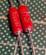
PRP PR9372 Series Leaded Metal Film for Audio
You wont be disapointed.
View attachment audio_pr9372_series_rev_f_nws-2 (1).pdf
Still waiting to take that on. A Nobel is there for the taking. We only disagree because one result rewrites physics.
Love to get another call from those folks.
Not really sure what you think is unusual. An audio signal runs around 1 volt RMS for maximum level. Not that unusual to have target signals 60 dB below that. Allowing for another 30 dB of sensitivity to higher order harmonics would give a signal level of 316 microvolts. So using a switch contact in series with a 100,000 ohm resistor driven by a ramp at that voltage should show a nice straight line on an oscilloscope monitoring the voltage across the resistor. Any deviation from a straight line would indicate non ohmic contact resistance that would result in harmonic distortion.
You wont be disapointed.
We were, and we do not, and will not, use PRPs ever since. As published elsewhere years ago, they have a reliability issue. The leads dropped off the end caps literally on bending for a whole batch of their 1W resistors. We asked for an explanation and wanted to know how it got through their QC. The only answer was they would replace the defect ones.
If you have one of these in a product, you have no idea when it might or might not fail. Ever since we switch everything to Dale RN55,65, ..... Never any issues, just as good in distortion, noise, ... you know what.
Cheers,
Patrick

Bruce Hofer of Audio Precision has given a lecture about the effects of resistors and capacitors in ultra low THD devices. I found it quite interesting and helpful.
It can be found here: YouTube
He doesn't give exact model numbers, but he does explain which types are the best for certain explanation. He also mentions that not all manufacturers give all the data required. Even if they provide a datasheet!
It can be found here: YouTube
He doesn't give exact model numbers, but he does explain which types are the best for certain explanation. He also mentions that not all manufacturers give all the data required. Even if they provide a datasheet!
Article
Ed Simon published, on Linear Audio Vol. 1, an interesting article: "Resistor non-linearity - there's more to Ohm than meets the eye".
The more common types of brands are tested, including Zfoil, RN, PRP etc.
And the winner is.........volumes | Linear Audio
Ed Simon published, on Linear Audio Vol. 1, an interesting article: "Resistor non-linearity - there's more to Ohm than meets the eye".
The more common types of brands are tested, including Zfoil, RN, PRP etc.
And the winner is.........volumes | Linear Audio
I will point out that virtually no graphs or numbers on any IC manufacter's datasheets involve anything but ordinary resistors such as Dale RN series or equivalent. In making reference designs for precision amplifiers we have tried to improve performance with series and parallel connections of ordinary SMT thin film resistors to no effect (this is at the limits of an AP, ~-130dB).
These ultra-precision resistors are used to make reference circuits for trim and ATE use but only to get things like 0.001% accuracy of gain to trim against.
EDIT - BTW I have measured sputtered thin film IC resistors at <2ppm/V at full 10V signals. VERY snall and 100's of atoms thick!
These ultra-precision resistors are used to make reference circuits for trim and ATE use but only to get things like 0.001% accuracy of gain to trim against.
EDIT - BTW I have measured sputtered thin film IC resistors at <2ppm/V at full 10V signals. VERY snall and 100's of atoms thick!
Last edited:
At around 32:30 he cautions specifically against the use of foil resistors in high end audio applications, due to low frequency thermal modulation distortion between 10-200Hz being much higher than would be implied from its specification, and this is apparently unexplained.It can be found here: YouTube
He doesn't give exact model numbers, but he does explain which types are the best for certain explanation. He also mentions that not all manufacturers give all the data required. Even if they provide a datasheet!
I’m not sure if this is mitigated in some foil resistor series or not or if it’s audible but is worth mentioning in the context of the conversation.
I have ben using the .25/.5/1.0 watt for at least 10 years and have never had any problems.We were, and we do not, and will not, use PRPs ever since. As published elsewhere years ago, they have a reliability issue. The leads dropped off the end caps literally on bending for a whole batch of their 1W resistors. We asked for an explanation and wanted to know how it got through their QC. The only answer was they would replace the defect ones.
If you have one of these in a product, you have no idea when it might or might not fail. Ever since we switch everything to Dale RN55,65, ..... Never any issues, just as good in distortion, noise, ... you know what.
Cheers,
Patrick
Last edited:
At around 32:30 he cautions specifically against the use of foil resistors in high end audio applications, due to low frequency thermal modulation distortion between 10-200Hz being much higher than would be implied from its specification, and this is apparently unexplained.
I’m not sure if this is mitigated in some foil resistor series or not or if it’s audible but is worth mentioning in the context of the conversation.
The explanation is pretty simple. Third harmonic distortion in a resistor results from the signal current heating and cooling the resistive element, changing its value with the signal waveform. At the peak of a sine wave, the resistor current is highest, so the resistor element is heated the greatest amount over the waveform’s cycle. At the zero crossings, there is nearly zero current flowing in the resistor, so the resistor is heated the least during a cycle, and it is able to cool down through conduction to ambient. Thus, the resistor is heated and cooled twice over one cycle of a sine wave, essentially modulating its temperature at twice the signal frequency.
Any resistor has a temperature coefficient of resistance, so its resistance value changes according to the resistor temperature. In the self-heating case above, the resistor value is thus modulated by the heating and cooling caused by the signal current, largely at twice the signal frequency. Modulate this with the original signal and you get a sideband a 3x the original frequency, or third harmonic distortion.
All resistors do this, and the temperature coefficient of resistance along with the thermal mass of the part are the factors that control the degree of resistance modulation. Obviously, a low temperature coefficient of resistance lessens this problem, but signal frequency and thermal mass also are factors. With high frequency signals, the heating and cooling happen too quickly for the resistor to change its temperature significantly, so there is little resistance modulation. With low frequency signals, or with resistors that have very low thermal mass, the resistor can easily heat and cool along with the signal current waveform, leading to greater thermal modulation.
The problem with foil resistors is that their temperature coefficient is low because it is the result of two opposing expansion coefficients. The foil heats, expands, and changes resistance, and the ceramic substrate that the foil is mounted to heats and shrinks by a complementary amount, largely cancelling the resistance variation. This technique works very well for DC and high frequency signals, and this is the temperature coefficient that they quote. The Vishay Z foil quotes 0.2 ppm/ºC, and this is extremely low. However, the substrate heating always lags the resistance foil heating, and if you get the frequency just right, the substrate’s contraction will be out of phase with the expansion of the resistance foil, essentially doubling the temperature coefficient of the foil itself.
Conventional resistors do not use this engineered substrate trick, and instead engineer the resistance film to have inherently low tempco. This approach does not lead to low frequency modulation effects, so they will not exhibit excess LF distortion.
Still, at the end of the day, you need to have a low temperature coefficient, or a large thermal mass to counteract this problem - simply not using foil resistors doesn’t address the fundamental tempco issue.
I think this is one of the reasons why some people don’t like SMD - the thermal mass of a small chip is much less than a larger leaded resistor. Still, modern SMD resistors like the Susumu RG have very low temperature coefficients, and don’t seem to exhibit these thermal problems unless you use really small sizes. The 3216 and 2012 sizes seem fine for most audio uses, and measure very well with the modern APx-555. FWIW, some older Dale and Mepco leaded resistors can have a tempco spec of ±100ppm, but often behave much better, closer to ±10ppm, depending on a particular value or lot, and also have a huge thermal mass. The Susumu RG basic spec is 0.1% with a 25 ppm/ºC tempco, and 10ppm is not that much more expensive, especially compared to quality low tempco through hole parts like the Dale CMF series.
The Susumu RG basic spec is 0.1% with a 25 ppm/ºC tempco, and 10ppm is not that much more expensive, especially compared to quality low tempco through hole parts like the Dale CMF series.
Monte you always need to scale these arguments to the problem at hand, as I said the reference design boards that we, TI, ESS, ship use ordinary cheap SMD resistors and still meet performance specs. In fact no one involved with doing these reference designs has a clue about these issues. I had to intervene once concerning a POTS/ADSL filter that used high K ceramics and could not work to spec.
Last edited:
Yes, and a good 'scaling to reality' as well. These distortion levels are ridiculously low, nearly impossible to measure, but still, the effect is there to be measured. What's comforting for me though is that measurements can be done to such low residuals now that if an effect can't be measured, it probably doesn't exist (or matter). That actually makes things a lot simpler for me.
We were, and we do not, and will not, use PRPs ever since. As published elsewhere years ago, they have a reliability issue. The leads dropped off the end caps literally on bending for a whole batch of their 1W resistors. We asked for an explanation and wanted to know how it got through their QC. The only answer was they would replace the defect ones.
Hello!
I ordered a few PRP PR9372 Series Metal Film resistors (0.5 & 1 Watt) to use for the first time. They look pretty and some folks claim that they perform well.
I remember coming across your particular post while reading about resistors and the different brands and took notice. However, I decided to go ahead with buying them anyway, since I wanted to try and 'upgrade' a few resistors on a diy kit of mine.
The resistors arrived and I did notice that the legs looked like they were attached a bit flimsily to the caps. I remember what you said and tried to be as gentle as possible with bending them. I was successful in not breaking any of them!
So, I replaced the old resistors on my kit with the PRP ones, without measuring each and every one of them. They all came packed in different baggies, according to value. I only checked the written values on the actual resistors before procceding.
To make a long story short, I encountered a problem after installing the PRP resistors and after a long troubleshooting by a process of elimination, I found out something wierd.
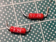
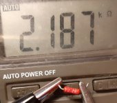
One of the resistors was supposed to be 2.2Ω (2R2 is written on it), but when I measured it I got 2.2kΩ. That is x1000 times more!!
I took my loop out just to make sure I wasn't reading it wrong, or the people that assorted them in the baggies didn't mix them up. It's clearly writing 2R2.
I'll post a picture of it shortly, so as to give me your thoughts.
I'm neither too knowledgeable, nοr too experienced, so i'm not sure if this is a common occurrence. I just though I'd share my story with you since I would like your experienced feedback.

- Home
- Design & Build
- Parts
- Resistor opinion