Greetings, ive been months trying to find a new solution for amplifier power output meters. since the LM3915/16 have been axed, and i have no idea how to program a microcontroller, its hard to find a new solution. so im here looking for some design help. LM3914 doesnt work for audio, been there done that. ive looked at a few VU meter IC's, im just using the LM391x as a reference as they are the most common and work well. ones ive looked for are the A277D, HA12010 and LB1411.
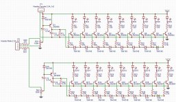
after about a month of one and off searching i found this design, which i copied into a stereo version on my EDA program (see image) but would like to add more "steps"
Stereo VU Meter
i breadboarded it but only had enough parts to make 5 leds. but i cant tell in that schematic, is the detection type linear, like the 3914 or is it tapered like the 3915/16? if its close to an audio taper, boom ill get some boards and try it out.
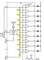
2nd idea, this one would be much more difficult i think, but would give the best results. Looking at the 3915's internal block diagram (see image) couldn't one just copy that design using descretes? just resistors and comparators basically.
3rd idea, does someone else have another good idea to get decent power meters that reads close to the purpose built IC's? ive seen a handful of pure discrete designs before but they behave like a 3914 where they raise to max level way to quickly.
as a last resort i started to snoop inside my tape decks and all i found was another dead part. The Sharp IR2E02. which would work, but i want 10-15 levels and not just 7. picky picky
ive been using this video has a side by side comparison between the 3 LM chips
YouTube
in the end i want to custom order PCB's for it. so i have no issue using chips, SMD parts or whatever else it takes.
If i forgot anything, let me know.
Any takers on this probably going to be way harder than it needs to be project?
after about a month of one and off searching i found this design, which i copied into a stereo version on my EDA program (see image) but would like to add more "steps"
Stereo VU Meter
i breadboarded it but only had enough parts to make 5 leds. but i cant tell in that schematic, is the detection type linear, like the 3914 or is it tapered like the 3915/16? if its close to an audio taper, boom ill get some boards and try it out.
2nd idea, this one would be much more difficult i think, but would give the best results. Looking at the 3915's internal block diagram (see image) couldn't one just copy that design using descretes? just resistors and comparators basically.
3rd idea, does someone else have another good idea to get decent power meters that reads close to the purpose built IC's? ive seen a handful of pure discrete designs before but they behave like a 3914 where they raise to max level way to quickly.
as a last resort i started to snoop inside my tape decks and all i found was another dead part. The Sharp IR2E02. which would work, but i want 10-15 levels and not just 7. picky picky
ive been using this video has a side by side comparison between the 3 LM chips
YouTube
in the end i want to custom order PCB's for it. so i have no issue using chips, SMD parts or whatever else it takes.
If i forgot anything, let me know.
Any takers on this probably going to be way harder than it needs to be project?
Attachments
Are you looking for a solution for volume production or just DIY? If the latter then there's no shortage of the discontinued LM3915 on eBay and Taobao.
A thought occurred to me - easier than doing a full discrete design, how about chaining 3 LM3914s in series - giving 30 linear steps - and only fitting LEDs to the steps you actually want to be displayed?
A thought occurred to me - easier than doing a full discrete design, how about chaining 3 LM3914s in series - giving 30 linear steps - and only fitting LEDs to the steps you actually want to be displayed?
Probably use less parts using 4 LM339's and would have two more steps to boot with having only one string of resistors to contend with and no diodes to match up.
But as mentioned a simple PIC chip can do this function with even less parts and more resolution, A PIC18F2550 has a 10bit A/D and 24 I/O's all you will need is a full wave rectifier for the input, This could easily give you a 20 step delay or a stereo 10 step display and with a simple mux trick get a stereo 20 step display.
All with just one chip for $2-$4 and maybe on opamp.
Some PIC's have an on board opamp that could be used for the input rectifier stage as well all done with one 28pin chip!
Just a few thoughts.
jer
P.S. Cool Circuit though !!
a new DIY design. i grabbed a few eBay 3915's but they all dont work very well. such as at NO input the first lights will flicker and in bar mode at higher levels like the 7th or 8th the first bottom lights will begin to dim and flicker again.Are you looking for a solution for volume production or just DIY? If the latter then there's no shortage of the discontinued LM3915 on eBay and Taobao.
A thought occurred to me - easier than doing a full discrete design, how about chaining 3 LM3914s in series - giving 30 linear steps - and only fitting LEDs to the steps you actually want to be displayed?
but chaining 3 3914's together would probably work PERFECTLY! just need to figure which 15 steps from the 30 would i need to select. just checked mouser as i was trying this, the DIP LM3914 is just now marked EOL. the SMD PLCC-20 is still good....for now
I had forgot to mention that the PIC18F2553 has a 12 bit ADC on it, I love this chip, having a Linear or Log display is just a matter of software, there is a thread on this subject somewhere here in the forum.
If you need more I/O then use a 40 pin pdip (or SMD if you prefer) PIC18F4553.
There are also some of the newer PIC's that have 12 A/D's as well here,
New/Popular 8-bit PIC MCU Products - Microchip Technology Inc
http://ww1.microchip.com/downloads/en/devicedoc/39887b.pdf
jer
If you need more I/O then use a 40 pin pdip (or SMD if you prefer) PIC18F4553.
There are also some of the newer PIC's that have 12 A/D's as well here,
New/Popular 8-bit PIC MCU Products - Microchip Technology Inc
http://ww1.microchip.com/downloads/en/devicedoc/39887b.pdf
jer
Last edited:
Here is just one version I have found, it is old but the schematic and code is there and can be adapted to whatever pic you decide to use.
The cool thing is that it shows how to multiplex more LED's using just a few lines.
https://www.edn.com/Pdf/ViewPdf?contentItemId=4319193
Found here,
picchip baragraph disply - Google Search
I did start such I project and made it work on a PIC18F4553 but never finished it. :/
I just remembered that the Arduino IDE already has a Baragraph example ( I think) and I have used it.
It's written in C on my uC32 (pic32) actually it was an example file for the Chipkit Basic I/O board.
I will see if I can find that code for you, it was only 8 step and the UC32 has a 10bit ADC, C is C and you can make it work on anything for the most part and make as many steps you want.
jer
P.S. here is a better refined search.
pic baragraph disply - Google Search
Attachments
Last edited:
Arduino code in C.
Arduino - BarGraph
One more, this one is in Assembly for the 16F877, actually the basis, Some help thread and is solved but you have to sign in to see the rest, there is a lot of this stuff out there, I hope this helps you if you decide to go this route, Good Luck with your project !!
Solved: Write A Code On The PIC Microcontroller PIC16F877A... | Chegg.com
Enjoy !!
jer
Last edited:
That Chegg link isnt of much help. I tried to make an account using one of those "10 minute fake email" sites, paid membership only.Arduino code in C.
Arduino - BarGraph
One more, this one is in Assembly for the 16F877, actually the basis, Some help thread and is solved but you have to sign in to see the rest, there is a lot of this stuff out there, I hope this helps you if you decide to go this route, Good Luck with your project !!
Solved: Write A Code On The PIC Microcontroller PIC16F877A... | Chegg.com
Enjoy !!
jer
but i do like the idea of using the PIC18F2550 for 2x 10-15 log bar graphs, but would take more time as ive never once even touched a micro. will also have to do some googling on how exactly to put a micro into a custom board, like what passives do i need around it.
another issue i found with the micro route is if i want 2x12 bar graphs, i would need either 24 outputs or multiplex it.
definitely need to read up on my micros!
going back a few posts mentioning the comparators, if for some reason we cant use a micro we can go that route. did find this design online on my lunch break today. i like this line from that design.
"The third opamp stage gives a logarithmic scale: it does this by means of a 5 stage feedback circuit. The various stages of feedback are switched in by the LED operating voltages and the diodes and resistors feeding back to the +ve input os the op-amp."
4QD-TEC: Audio LED VU meter
Ya, I haven't signed in to Chegg yet I may give it a try later.
I didn't realize until after I made the post that the code was incomplete /buggy or something.
Anyhow as far a extra parts go using the PIC18 there is one Bypass cap and that's it.
They have a built in osc. so you don't even need to use a Xtal, unless you you want to build a clock or something that requires precision timing .
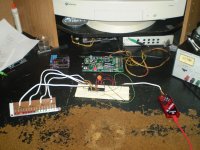
If you look closely at my set up there is no Xtal !!
I may have a video of the thing running on my FB page, I don't remember its been a few years since I had gotten it out again.
I started it because of a friend that had bought a couple of LM3915 boards for some ridiculous price and ended up destroying the boards trying to solder them, ( Newbie ) .
So, I was going to build it for him but his whole project kinda bombed (Big 4 channel 150watt chip amp) and put it away for a while.
Multiplexing the banks of LED's is a very simple straightforward piece of cake as the pins can either sink or source the current.
There are many ways to do that as shown in the EDN link I posted earlier, or by using the MCP2317 16 bit expander GPIO port, there are two types SPI and I2C and 8 bit wide versions as well.
Just click on the Fig.1 and other blue print (link) in the PDF and it will open up the code and schematic pages for you.
There is a cool +100 step bargraph display available on line as a kit using a PIC and a bunch of Expander ports, But I could not find the source code open source so that I could build it myself.
But it is not hard to do, although I have not hooked any of my Expander's to try yet,
Got too much going on lately.
I got in to micro's just a few years ago (5) Thanks to Microchips FREE Sample program out of necessity !!
I needed something to control the preamp I am planning for my Desktop ESL system.
I had used 3 or 4 of the LM3914 stacked up before for a power supply output indicator in 2003 and it worked good for that project but I had found that they weren't very linear at all and the chip to chip tolerances was very poor, considering how old they were it was understandable.
Yup , you can use an Opamp to create your log conversion as this saves Big Time on the programming and special value resistors, but you need a full wave rectifier stage ahead of the PIC anyhow, and one dual opamp can handle this or a quad for stereo and use two of the analog inputs on the PIC.
Q4tec is a good example of that, typically most Logarithmic converters I have seen use a BJT in the feedback loop, never seen one using a diode before, If had I guess I just didn't notice since I never had a requirement for one..... Yet !
I'll have to find the conversion table for linear to log in a 10bit and 12bit format steps to see how much of a difference there may be in accuracy between the two, but the cost difference between the 18F2550 (10bit) and 18F2553 ( 12bit ) is nil.
I always go for the one with more resolution if it available.
jer
I didn't realize until after I made the post that the code was incomplete /buggy or something.
Anyhow as far a extra parts go using the PIC18 there is one Bypass cap and that's it.
They have a built in osc. so you don't even need to use a Xtal, unless you you want to build a clock or something that requires precision timing .
If you look closely at my set up there is no Xtal !!
I may have a video of the thing running on my FB page, I don't remember its been a few years since I had gotten it out again.
I started it because of a friend that had bought a couple of LM3915 boards for some ridiculous price and ended up destroying the boards trying to solder them, ( Newbie
) .So, I was going to build it for him but his whole project kinda bombed (Big 4 channel 150watt chip amp) and put it away for a while.
Multiplexing the banks of LED's is a very simple straightforward piece of cake as the pins can either sink or source the current.
There are many ways to do that as shown in the EDN link I posted earlier, or by using the MCP2317 16 bit expander GPIO port, there are two types SPI and I2C and 8 bit wide versions as well.
Just click on the Fig.1 and other blue print (link) in the PDF and it will open up the code and schematic pages for you.
There is a cool +100 step bargraph display available on line as a kit using a PIC and a bunch of Expander ports, But I could not find the source code open source so that I could build it myself.
But it is not hard to do, although I have not hooked any of my Expander's to try yet,
Got too much going on lately.
I got in to micro's just a few years ago (5) Thanks to Microchips FREE Sample program out of necessity !!
I needed something to control the preamp I am planning for my Desktop ESL system.
I had used 3 or 4 of the LM3914 stacked up before for a power supply output indicator in 2003 and it worked good for that project but I had found that they weren't very linear at all and the chip to chip tolerances was very poor, considering how old they were it was understandable.
Yup , you can use an Opamp to create your log conversion as this saves Big Time on the programming and special value resistors, but you need a full wave rectifier stage ahead of the PIC anyhow, and one dual opamp can handle this or a quad for stereo and use two of the analog inputs on the PIC.
Q4tec is a good example of that, typically most Logarithmic converters I have seen use a BJT in the feedback loop, never seen one using a diode before, If had I guess I just didn't notice since I never had a requirement for one..... Yet !
I'll have to find the conversion table for linear to log in a 10bit and 12bit format steps to see how much of a difference there may be in accuracy between the two, but the cost difference between the 18F2550 (10bit) and 18F2553 ( 12bit ) is nil.
I always go for the one with more resolution if it available.
jer
- Status
- This old topic is closed. If you want to reopen this topic, contact a moderator using the "Report Post" button.
- Home
- Design & Build
- Parts
- Modern Day LM3915 descrete replacement.