As the pictures shows, what's the purpose of the wires wound around the electrolyte?
Pictures source: Update My Dynaco
Pictures source: Update My Dynaco
Attachments
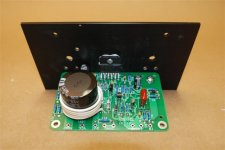
...using the cap can as a handy coil form...
Most likely.
An inductor in the output line, using the cap can as a handy coil form? Is that coil in series with the speaker connection? I THINK I see a parallel R15 on the board. That would be consistent with my theory.
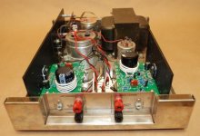
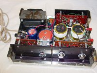
Yes, Dynaco did this back in the 60s, like in this Stereo 120.
http://davidreaton.com/wp-content/uploads/2016/08/Dyna-120-with-cover-off.jpg
Last edited:
On one hand winding around a metallic conductive coil former, such as the electrolyte cans, would cause an interwinding capacitance that shorts all turns capacitively to the coil former, hence it would result in a higher Q me thinks wouldn't it? If so, on a general note one would think it's a rather suboptimal choice if its purpose is to dampen any spurious oscillations caused by difficult loads/speaker cabling and mitigate RF ingress.
In practice the wire Dynaco are using has a thicker insulation compared to magnet wire which in turn would lower the capacitive effects between the windings and the electrolyte can, also the output stage in the Dynaco 120 as an example is outfitted with quite slow 2N3055 transistors and probably sufficient for the design.
ps. Thanks Rayma for the picture link to David Reaton's web page, it's attached now below for future generations admiration.
Attachments
Last edited:
The circuit impedance will be low enough that stray capacitance is not a serious issue. The low Q comes from three places:
1. the capacitor can (if aluminium) will be a shorted turn (so also lowers inductance) but aluminium is not such a good conductor as copper.
2. even if the can is not aluminium but plastic, the innards of the capacitor are likely to be lossy at RF.
3. such a coil needs more turns than an air-cored version, so more copper losses
- Status
- This old topic is closed. If you want to reopen this topic, contact a moderator using the "Report Post" button.
- Home
- Design & Build
- Parts
- Wire wound around the lytes does what??