At the moment I am building a rather large inductor on an ETD 54 core. I need to get a gap of around 1.5mm - 2.0mm in order to prevent core saturation. It seems gapped cores are not available for purchase. Upon searching, I found two shops (one in California, one in NZ) that grind gaps into the cores. Emailed both, but no reply. The only other way I can think of is to use a butt gap (put a spacer on all 3 legs). This is not a very good solution though because the cllips probably won't fit with the spacers in the core 
I always hate the metal clips and such for things like ETD and EC cores. What I do is carefully saw away the side pieces on the bobbin (if necessary, likew ith the common ETD bobbins) and use electrical insulating tape to hold the core halves together. By this I mean the standard mylar transformer-type tape, not the black vinyl electrician's crud. If the finished inductor is varnished afterwards, it will hold together forever. You can also use spacers for gapping the core without fear of cracking anything. Pieces of mylar sheet make good stable gapping shims. For large gaps, pieces of popsicle stick or tongue depressor also work very well, especially if the inductor is varnished. Using tape is standard practice in the industry for holding core halves together in ferrite transformers. Polyurethane varnish would be a good substitute for transformer varnish. Dip the finished product for about 15 minutes, let it hang insde the varnish can until it stops dripping, then bake it at 100C or so for an hour. This is pretty final, so you only want to do it after you're satisfied with the inductor value.
The opperating frequency is 200kHz, with an average current of 10A. The skin is quite thin at this frequency. Using normal winding wire, the number of parallel windings required to reach an acceptable cross sectional area is quite substantial. I don't think it will be possible to wind the coil (and achieve acceptable performance) without using litz wire.
wrenchone said:I can't see any really compelling reason why you would need litz wire. What is your operating frequency?
Depends largely on the amount AC ripple current. That ripple current flows mainly near the outside of the wire and can heat up the thing severely. Also the proximity effect can make things really bad in just an inductor at that frequencies.
For such occasions I make my own “litz” wire myself of a sufficient amount 0.3 – 0.4 mm paralleled enameled wires. You usually need something of 3 meters of wire, often less. I span the wires between two hooks, one hook in the vice and the other one in the electric drill. Et voila ....
If you use gapping by just using spacers between the core halves it is wise to strap a copper foil short around the whole trannie to minimize EMI.
Cheers
The average ripple current on the inductor will be 4.82A. With an average DC current of 10A flowing in the inductor, I calculated a cross section of around 3.6 sq mm would be required. This amounts to 50 strands of 0.3mm wire. Just twisting 50 strands together I didn't think there would be even current distribution between the individual wires?
Wait a minute - 4.82 A average ripple current? How did you get that? What is the p-p value? Backing up a few steps, how did you calculate the inductance required, what is the value, an what are your rail voltages? That much ripple current would require substantial downstream filtering to keep from lighting up the neighborhood with RFI. Are you using one of the standard switching amplifier chips, or is this a homebrew sort of affair? Also, 10A DC current indicates that your'e tring a monster amp or PA sort of setup. That much current would make most woofers cough their guts out on the floor...
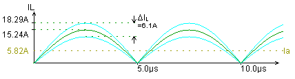
Sorry, those figures are not quite right. I just had another look over my calculations. The inductor is not actually the output filter inductor, it is from another part of the amplifier. Anyway, I have been doing some simulations and here is a graph of the inductor current:
Attachments
- Status
- This old topic is closed. If you want to reopen this topic, contact a moderator using the "Report Post" button.
- Home
- Design & Build
- Parts
- Gapping ETD Cores?