2SK97 equivalent?
Hi - Im working on a Sansui AU-X1 - I have my work cut out for me.
I just cant get the offset stable in either power amp module. I have changed out many transistors but the problem is at the front end and near the back end also. I am suspecting that both 2SK97 dual fets are bung.
Replacements I am thinking are potentially 2 x 2SK117 or 2SK170.
Any other suggestions? Should these pairs be matched?
Thanks!
Thanks Jon. Am checking all the voltages at the input stage and they are off - some up and some down from what I meant to be getting.Plus the DC offset is shooting around from 0 up to 4 or 5 volts.
These amplifiers are known to be basket cases in some cases and I have measured the outputs of the preamp - I saw a couple of 1v spikes and I suspect some spikes may have wiped out the FETs on the input of the power stage. Just a theory at this stage however the voltages I am supposed to be getting on the FET S and D pins are way too high.
These amplifiers are known to be basket cases in some cases and I have measured the outputs of the preamp - I saw a couple of 1v spikes and I suspect some spikes may have wiped out the FETs on the input of the power stage. Just a theory at this stage however the voltages I am supposed to be getting on the FET S and D pins are way too high.
Hi there-
I'm having a hell of a time with a Sansui AU-X1 - both power modules are giving me way-off readings. This is despite checking all power is good, subbing different transistors in and out, testing all resistors, replacing all zeners and normal diodes. I am getting similar wonky readings on both units.
I want to definitely rule out the input FET as a culprit - I know it is "rare" for these to go "pop", however in this amplifier, anything is possible including spikes/surges/oscillation coming in from the preamp section.
Any basic tests for testing either channel of this FET? Would the testing measures shown on this site work, or would I need to apply a voltage to the chip? If so, to which pin/s?
Meter Check of a Transistor (JFET) | Junction Field-effect Transistors | Electronics Textbook
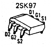
The service manual illustrates the pin assignment of this DIP dual JFET. Always use a proper manual if available - especially for a complex monster that is full of unobtanium components like this one. PS - Note that the simple tests shown at the Electronic Textbook site require the device to be disconnected from the circuit but that may not be necessary if you simply measure the DC wrt ground at each terminal and compare for both pairs of JFETs in both channels. Post measurements here if you are still unsure what the comparison means.
Sansui AU-X1 - Manual - Super Integrated Amplifier - HiFi Engine
Sansui AU-X1 - Manual - Super Integrated Amplifier - HiFi Engine
Attachments
Last edited:
Cheers Ian - I have the manual and have expelled the FETs. Am testing the amp with sacrificial MJ-type pre driver and outputs installed. I want to test the 97's and if they are bung, look for a suitable sub (which will be tricky in itself also, the only close one I can find so far is the LSK389). cheers!
Did you take any measurements comparing the 2SK97's in-circuit? If you are going to substitute so many semis, first record adequate reference voltages around them or ensure that you have close equivalent types to what you began with. If the Jfets are functional, they would be unlikely to show the same problem in all 4 , so I would try to leave them exactly where they were to avoid matching hassles.
I'm not sure anyone other than a well-experienced tech (as in - knows more than a bit about VFET designs of old) would be able to get this variation working properly from scratch. Member Ilimzn is well versed in them so perhaps he'll drop by and suggest the best course of action from here.
I'm not sure anyone other than a well-experienced tech (as in - knows more than a bit about VFET designs of old) would be able to get this variation working properly from scratch. Member Ilimzn is well versed in them so perhaps he'll drop by and suggest the best course of action from here.
Last edited:
Hi Ian - yes I did start by taking measurements with the 2SK97 in circuit. However voltages around them and the first few transistor were quite far off what they were meant to be. All semis' test OK so I thought the remaining issue could be the FET. For example - I am meant to get these measurements in circuit:
Measurement between ground and both sources is meant to be 0.39v, Im actually getting 1.15v. Measurement between ground and drain is meant to be 1.6v, but Im getting 8v. This of doesnt mean the FET is bung, but it could do, so it would be nice to eliminate it if poss. The main problem is that I never had a good working point of reference in this amplifier to start with unfortunately.....
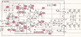
Argh, this amplifier is complex. Please see relevant sections of schema attached. Cheers!
Measurement between ground and both sources is meant to be 0.39v, Im actually getting 1.15v. Measurement between ground and drain is meant to be 1.6v, but Im getting 8v. This of doesnt mean the FET is bung, but it could do, so it would be nice to eliminate it if poss. The main problem is that I never had a good working point of reference in this amplifier to start with unfortunately.....
Argh, this amplifier is complex. Please see relevant sections of schema attached. Cheers!
Attachments
Chances that jfets on both channels being bad at the same time is low.
You can always remove the jfets and test separately in a jig to characterize them.
Is your amp oscillating?
Bias generator working.
For the fun of it, I simulated the design in ltspice awhile ago.
You can always remove the jfets and test separately in a jig to characterize them.
Is your amp oscillating?
Bias generator working.
For the fun of it, I simulated the design in ltspice awhile ago.
Last edited:
In your other thread I posted the ltspice sim of this design. I have tried a number of different jfet that I have libs for, 2sk117,2sk170,lsk170A(B),J310, they all seem to work.
If you look at D02 they wrote 9.6V which is correct, it is to be the same as D01, it has to be, it is a balanced diff pair, they must be the same or it is out of wack.
I do not think that 1.15 Vsource is wrong, it is probably a jfet with slightly higher Idss, with a J310 I am getting 2.45V
Sansui is throwing you a curve, it is a mistake.Measurement between ground and drain is meant to be 1.6v, but Im getting 8v.
If you look at D02 they wrote 9.6V which is correct, it is to be the same as D01, it has to be, it is a balanced diff pair, they must be the same or it is out of wack.
I do not think that 1.15 Vsource is wrong, it is probably a jfet with slightly higher Idss, with a J310 I am getting 2.45V
Thanks a lot rsavas, that should give me some more voltages to work from within the circuit for testing purposes.
In the meantime I tried to measure the VGS (off) and Idss on both sides of the 2sk97 and got between 1.8-3mV on both sides, and absolutely no reading in mA on either side.....
In the meantime I tried to measure the VGS (off) and Idss on both sides of the 2sk97 and got between 1.8-3mV on both sides, and absolutely no reading in mA on either side.....
Attachments
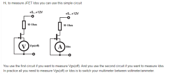
I have never used that method to measure Idss. I know you want Vgs to be 0. You should measure Rds simply with the ohmmeter across D/S.and absolutely no reading in mA on either side.....
Take a look at this test method
Simple circuit lets you characterize JFETs | EDN
Also
https://www.mikrocontroller.net/attachment/82476/Siliconix_AN73-7_prt.pdf
Last edited:
- Home
- Design & Build
- Parts
- Testing a 2SK97 FET