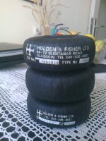
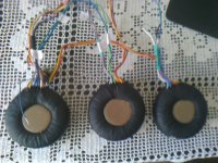
I can get one of these cheap and I need a transformer for my next project (6W stereo amp based on TDA1521A). It's a Holden&Fisher toroidal that seem to be well regarded. It's 88mm x 34mm big with 115/230V primary and secondaries that measure 2x10v and 1x22.5v. Based on the size, I'd assume that it's at least 50VA, so it should be fine for my project, but how do I determine which of the secondaries to use? My guess is that 2x10V was used for symmetrical power supply used by power amplifier of sorts. That would work for me because I need +-12V (up to +-20V) to power the TDA1521A. Can I measure anything else to determine current capabilities of the two secondaries?
Maybe someone can recognize it from a device. I know they were used in Chrome bumper NAPs and few other good quality devices.
The pics are below
Thanks!
Maybe someone can recognize it from a device. I know they were used in Chrome bumper NAPs and few other good quality devices.
The pics are below
Thanks!
Attachments
Last edited:
Measure the DC resistance of the windings. The two 10 volt windings should be similar and if the combined resistance of these two is lower then that 22 volt winding then it would appear they would have greater current capacity.
You can also load each winding with a suitable resistor (value chosen to draw the same current) and the winding with least droop should be the higher current ones.
You can also load each winding with a suitable resistor (value chosen to draw the same current) and the winding with least droop should be the higher current ones.
Hi,
I measured what you suggested, but got somewhat inconclusive results. The two 10V windings measure around 1.2ohms combined, although it's hard to tell exactly, as my multi-meter isn't super accurate with such low resistances. The 22V secondary measures around 0.7V which would indicate that it's higher current. Also tried to measure the drop using a 100ohm resistors with 15V connected to the 115V primary, to be safe with lower voltages. The two 10V secondaries (now reading around 2.6V) show voltage drop around 0.07V across the 100ohm resistor and 22V secondary shows around 0.095V of drop. So it looks like the two secondaries have similar current capabilities. Voltage drop would indicate that the 10-0-10V is slightly more capable.
Would you agree?
Judging by the size of the transformer, I'd guess that it's rated 60-80VA. If my estimate is correct, I'll have 30-45VA for the 10-0-10V secondary I need for the symmetrical power supply for my project. It should be fine for a 2x6W amp.
Cheers,
Bane
So 0.6 ohms for each 10 volt secondary and 0.7 ohms for the single 22 volt one. That seems to indicate the 22v one is the higher rated.
I would try this on full mains with more suitable resistors tbh. Mains voltage halogen lamps have a low resistance when cold/cool and so should draw respectable current.
Nothing bad is going to happen, even if you momentarily overload it.
I would try this on full mains with more suitable resistors tbh. Mains voltage halogen lamps have a low resistance when cold/cool and so should draw respectable current.
Nothing bad is going to happen, even if you momentarily overload it.
You can also measure the regulation by loading each secondary. If you assume that the voltage drops by approx 10% at full load.
Slowly load up each secondary and measure the ACV.
The full load may not be an ideal rating of that secondary but it will indicate which windings are capable of what currents.
Slowly load up each secondary and measure the ACV.
The full load may not be an ideal rating of that secondary but it will indicate which windings are capable of what currents.
Last edited:
Multimeters can not be trusted measuring very low ohm resistors, say 5 ohms and below, because you are also measuring *all* small resistances in the path (switch contacts, banana plug contact resistance, test probe resistance, test wires, surface contact between probes and what you are measuing, etc.) which add up to somethying between 0.3 and up to 1.8 ohms.
It wouldn´t be that bad if it were *constant* so you can reliably substract it from displayed value but it´s random and depends on many things , so ....
What I do is to separate "current supply" and "voltage measurement" functions which otherwise are both (unreliably) done by your meter.
Get a PC type supply (everybody has an old one somewhere collecting dust) and a 5 ohm resistor, 5W or higher.
This is a crude but workable 1A "constant current" supply; in any case we are not after 1% precision values but it´s a *comparison* between 2 low resistance values, so....
Apply said "1A DC" to winding under test and measure DC voltage across it ... your scale is now "1 Volt DC per Ampere" , meaning, say, 50 mV DC across winding means 50 milli Ohms (0.050 Ohms) and you have about 10% precision or better
Try that with a regular multimeter !!!
I use that setup to measure contact resistance in switches, jack/plug contacts, relay contacts, *Fuse* resistance, etc.
Eye opening and that´s an understatement
Thanks guys, great ideas.
@KatieandDad, that's a good point. But I'd need a 30W resistor if I were to load it to the assumed full load, right?
@JMFahey, great stuff as always. I don't have a PC supply, but I'll try to get one. What does the 5 ohm resistor do in that arrangement? I put it in parallel with the 5V DC output from the power supply to load it to 1A?
Thanks again!
Update: I tried loading the secondaries down with halogen bulbs because that's what I had available at the moment. I wired two, then four 12V 35W halogen bulbs in series and powered them with each of the two secondaries.
The secondaries measure 20.3V and 22.7V without load.
With two bulbs in series, the secondaries measure 14.8V and 17.6V. That's 27% drop for the first one and 22.5% for the second one.
With four bulbs in series, the secondaries measure 16.4V and 19.3V. That's 19.2% for the first one and 15% for the second one.
Judging by that, it seems like they are relatively close, but the second secondary seems to be a bit more capable. Now, I'm trying to interpolate what the load would be to achieve the 10% drop (don't have anymore bulbs)
If my math is correct (and it probably isn't), by powering two bulbs in series with 20V instead of 2*12=24V, they draw ~20% less than the original 70W which comes down to 56W (should be 56VA with resistive load?). When we put four bulbs in series, the series resistance is doubled, so the current is halved to around 30VA. If my center-tapped secondary drops 19.2% at 30VA it's probably not even close to 30VA rating, right? The drop should be around 10% at the target "max" load. Although it's quite possible that I got the math wrong because bulb resistance isn't constant and rises with the current.
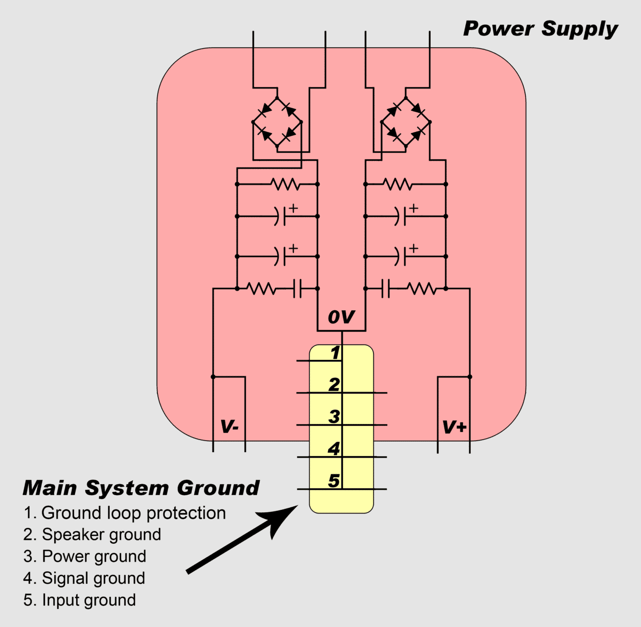
Now I'm thinking about a different approach of getting the +-12V rail voltage out of this transformer while maximizing the current capability. What if I rectify the two secondaries independently, ignoring the center tap on one of them, that would get me 25-30VDC on each of them. Then I could put one buck converter on each of them, drop down to 12V and then connect them back to back, like shown on this schematic. That should work, in theory. I'd be able to squeeze out almost every single milliamp, as buck converters should be pretty efficient. Another alternative are regulators, but I'd need to dump a ton of heat.
The secondaries measure 20.3V and 22.7V without load.
With two bulbs in series, the secondaries measure 14.8V and 17.6V. That's 27% drop for the first one and 22.5% for the second one.
With four bulbs in series, the secondaries measure 16.4V and 19.3V. That's 19.2% for the first one and 15% for the second one.
Judging by that, it seems like they are relatively close, but the second secondary seems to be a bit more capable. Now, I'm trying to interpolate what the load would be to achieve the 10% drop (don't have anymore bulbs
)If my math is correct (and it probably isn't), by powering two bulbs in series with 20V instead of 2*12=24V, they draw ~20% less than the original 70W which comes down to 56W (should be 56VA with resistive load?). When we put four bulbs in series, the series resistance is doubled, so the current is halved to around 30VA. If my center-tapped secondary drops 19.2% at 30VA it's probably not even close to 30VA rating, right? The drop should be around 10% at the target "max" load. Although it's quite possible that I got the math wrong because bulb resistance isn't constant and rises with the current.
Now I'm thinking about a different approach of getting the +-12V rail voltage out of this transformer while maximizing the current capability. What if I rectify the two secondaries independently, ignoring the center tap on one of them, that would get me 25-30VDC on each of them. Then I could put one buck converter on each of them, drop down to 12V and then connect them back to back, like shown on this schematic. That should work, in theory. I'd be able to squeeze out almost every single milliamp, as buck converters should be pretty efficient. Another alternative are regulators, but I'd need to dump a ton of heat.
As your requirement is for such a small transformer anyway (relatively speaking), would it not be better to obtain one suitable for the project ?
There are always ways and means but sometimes its best to stand back and take stock.
One other approach would be to make two identical AC coupled amps and run each from its own secondary. The slight difference in supply voltage between the channels would not matter and you would end up with a dual mono amp that maximises use of the transformer you have.
Hi Molly,
getting a custom transformer is certainly an option. I wanted to try to use these because they seem cool (and I bought two), but if it proves to be too big of a pain, I'll just get a new one. I'm poking around for more options because it's fun to learn new stuff.
I was hoping that my math in the previous post was wrong. If I can get 30VA out of the 10-0-10V secondary it should be perfectly fine for a small 2x6W amp that I plan to run at TV level all the time anyways.
thanks for all the help!
getting a custom transformer is certainly an option. I wanted to try to use these because they seem cool (and I bought two
), but if it proves to be too big of a pain, I'll just get a new one. I'm poking around for more options because it's fun to learn new stuff.I was hoping that my math in the previous post was wrong. If I can get 30VA out of the 10-0-10V secondary it should be perfectly fine for a small 2x6W amp that I plan to run at TV level all the time anyways.
thanks for all the help!
I would say that for an application like you suggest then it is going to be fine anyway. A small audio amp with typical program (music) will draw quite a small overall current.
The bulbs give a rough idea of current ability but you have to remember that small voltage differences across a bulb make a massive difference to its resistance, especially when severely under running the filament. The quoted wattage of the bulb is pretty meaningless as such here.
The bulbs give a rough idea of current ability but you have to remember that small voltage differences across a bulb make a massive difference to its resistance, especially when severely under running the filament. The quoted wattage of the bulb is pretty meaningless as such here.
It should be fine. Just add a high pass filter in front of the amp and judge by ear the point where you can not hear any difference with or without. If you are designing the amp then that can be designed in from the start, if its an off the shelf amp then its just a case of a cap and resistor up front at the input.
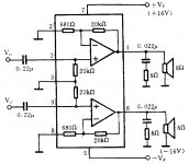
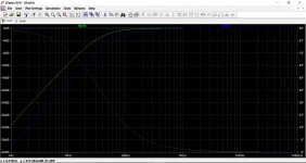
I'm building a simple amp based on TDA1521A, using datasheet example as the starting point. By default it has 0.22uF input cap and internal 20K resistor to ground. If my math is right, that should form a high pass filter at 36Hz.
I calculated -3b cutoff frequency for my speakers inside a vented cab at around 90Hz. I was going to reduce 0.22uF with 0.1uF which should cut around 80Hz...that should be close enough and still cut extra bass. At least on paper it makes sense
I calculated -3b cutoff frequency for my speakers inside a vented cab at around 90Hz. I was going to reduce 0.22uF with 0.1uF which should cut around 80Hz...that should be close enough and still cut extra bass. At least on paper it makes sense
Attachments
thanks! I'll leave the input capacitors out for testing and will try to clip both values and test. If there's no change in bass response, I'll stick with 0.1uF, otherwise I might look for a 150nF.
Cheers and thanks all for the help! I'll report when I build the amp. Got the chassis today, waiting for PCBs to be fab'd.
Cheers and thanks all for the help! I'll report when I build the amp. Got the chassis today, waiting for PCBs to be fab'd.
- Status
- This old topic is closed. If you want to reopen this topic, contact a moderator using the "Report Post" button.
- Home
- Design & Build
- Parts
- Help identifying the transformer