Ultimate caps for electronic filter (range 500pf-10nf)
Hi,
I looking for a capacitor that match to the z-foil resistor in an electronic filter for a DAC (ES9028PRO).
The values are from 510pF to 10nF.
I thinking about Amtrans AMCH or Orange drop or Vishay Kp1830 or MKP1837 or??.
This comparision - Humble Homemade Hifi - Cap Test - gives some example but setup is for passive loudspeaker use and not digital filtering.
What is your recommendations and experiences?
Last edited:
I posted a similar question on Styroflex caps, got some advice but I went ahead to oerder some Toshin PPSD caps instead. Awaiting for delivery to test them out. Keeping my fingers crossed that they’ll sound fab cause it made of copper foil. Will be using them on I/V stage.
Cheers
Cheers
Silver mica & polystyrene.
I though polypropylene was the best material for caps..
Why is Mica and styroflex better sounding?
Foil vs metalized...most of PP caps are foil metalized. which foil caps are not metalized?
SM & polysterene are better dielectrics.
Thanks for input.
Having read a bit more on Silver Mica then it seems like plastic caps are made as it is cheaper...
Charcroft makes some SM...any experiences with those?
I'm not sure what sort of digital filter uses caps and resistors; surely digital filters use software and logic? Also unclear how a cap can "match" a resistor.Neslo said:I looking for a capacitor that match to the z-foil resistor in a digital filter for a DAC (ES9028PRO).
The best dielectric is the one which best fits the intended task. Sometimes this is air, sometimes plastic, sometimes ceramic. Sometimes stability is needed, sometimes low loss, sometimes high loss, sometimes linearity. That is why there are lots of capacitor types. Almost every one of them is good for something.merlin el mago said:Best dielectric air followed by teflon.
I'm not sure what sort of digital filter uses caps and resistors; surely digital filters use software and logic? Also unclear how a cap can "match" a resistor.
The best dielectric is the one which best fits the intended task. Sometimes this is air, sometimes plastic, sometimes ceramic. Sometimes stability is needed, sometimes low loss, sometimes high loss, sometimes linearity. That is why there are lots of capacitor types. Almost every one of them is good for something.
You are correct it is not digital filter but a electronic filter with resistors and caps around a discrete opamp
when is a cap not a cap? check the self resonant frequency
low series inductance is good for low passing D-S DAC shaped noise at MHz
which makes NP0 smt chip caps the better choice - and their audio quality as measured by distortion products is fine by Bruce Hofer of Audio Precision
low series inductance is good for low passing D-S DAC shaped noise at MHz
which makes NP0 smt chip caps the better choice - and their audio quality as measured by distortion products is fine by Bruce Hofer of Audio Precision
Last edited:
low series inductance is good for low passing D-S DAC shaped noise at MHz
which makes NP0 smt chip caps the better choice - and their audio quality as measured by distortion products is fine by Bruce Hofer of Audio Precision
Absolutely correct. I tested the distortion of some 0.1µF caps recently on an APx-555, and very small NP0 ceramics perform really well, despite the obscene field strengths placed on the dielectric. Comparing 100V 1206 size Kemet and Murata C0G caps with 50V F-Dyne polystyrene and 200V Component Research hermetic foil teflon showed that even at high signal currents - 25mA peak at 2kHz - they all behave basically the same, scraping the analyzer residual at around -142dBc of 2nd harmonic. When a bias voltage was also applied, then the ceramics started to 'fold up' a little sooner than the film caps, but still, if you aren't blasting them with 25mA signal along with 3V+ bias, they are all indistinguishable.
The small size of C0G ceramics also makes them far better caps when dealing with extremely HF signals. It also allows the layout to be much smaller and cleaner, and the lack of accidental electrical coupling from some source of garbage to the outer foil of a film cap might help to prevent more junk in the filter output than some tiny ephemeral increase in linearity.
Finally, SMD C0G caps are more consistent, and none will suffer distortion from faulty electrode termination. The Component Research parts avoid that by 100% unit testing, and they cost a fortune, but for a satellite, I guess it's worth it. But, unless you do 100% screening, a film cap can have termination problems that will cause much more distortion than was measured above, and MLCCs will not do that.
In case anyone is interested, here is the raw data from the tests I referred to in my earlier post. I used the APx-555 oscillator and analyzer with the 20Ω unbalanced generator mode. The caps were driven through an impedance probe that I built, which drives the caps with an unbalanced drive through a 100Ω RN75 resistor to the cap, which is then attached to ground. The probe provides two Kelvin connections, one around the 100Ω resistor, and one around the cap under test. For this test, I only used the Kelvin connection around the cap under test to measure the voltage across it, along with any distortion products.
To prevent the DC bias from annoying the AP generator, the probe contains a composite 480µF coupling cap to block DC from the generator. This was made from 48 10µF 200V metallized polypropylene caps individually screened for distortion. The test jig was a sheet of unetched FR4 used as a ground connection for the caps and impedance probe. A simple two stage RC filter was added to the DC source to clean up any power supply noise. It used a 421Ω series R and 470µF cap to ground, another 421Ω series and 470µF shunt, and then a 2K21Ω series resistor to the cap under test. The 480µF generator coupling cap had to be charged by this network, and the resulting time constant was pretty long, requiring me to wait a minute or so for the DC bias to settle before starting measurements.
The measurements were done with 64 averages of a 512K point FFT, and the data was exported and copied to the spreadsheet. The odd stimulus frequency of 1.99805kHz was chosen so that the harmonics line up with the 192kHz sample rate FFT bins accurately.
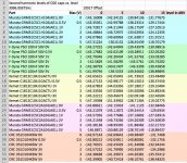
The spreadsheet contains one row for each cap tested at a specific DC bias level. Each column shows the level in dBV of the harmonic, at a particular 2kHz drive level. Note that this is relative to the drive level across the cap, and is not a true dBc measurement. So, as drive level increases, so does the harmonic level. At 2kHz with the ~120Ω drive impedance, the 0.1µF cap voltage is only about 0.57dB less than the drive level, so a dBc value can be obtained by subtracting the drive level minus 0.57dB from each harmonic voltage.
Looking at the 2nd harmonic data for the first Murata part, at 0dBV drive, the distortion level seems to drop with increasing bias. This is likely an increase of distortion from the cap, cancelling the analyzer residual. This is a problem with measurements so close to the analyzer residual - sometimes a ‘decrease’ in measured distortion actually means that the DUT has more distortion, which cancels the residual analyzer distortion yielding a lower number. Long and short, an ideal cap would exhibit the same analyzer residual for all DC bias.
2nd harmonic distortion is a good indication of dielectric saturation, which is what can be expected when a DC bias is added to the signal. If the cap does not change distortion with increasing DC bias, then the dielectric is still linear. But, as can be seen, all caps tested ‘squish up’ with DC bias, the difference being the signal and DC bias level where the ‘squish’ is noticeable.
So, it should be clear that all of the caps, including the space grade CRC foil teflon, will saturate if you drive them hard enough. The CRC teflon was unchanged at 0dBV drive with 0 to 5V bias, whereas the ceramics started to show signs of saturation at 0dBV drive with increasing DC bias. Still, at 5 and 10dBV drive, the CRC showed signs of saturation with increasing DC bias as well, despite the fact that the teflon cap was physically very large (~0.5”D x 1”L)
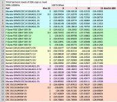
I also included the third harmonic data from the same tests, although DC bias is not expected to change the 3rd harmonic level at all. Fortunately, that is shown by the measurements, adding some confidence to the procedure and the conclusions that can be drawn.
To prevent the DC bias from annoying the AP generator, the probe contains a composite 480µF coupling cap to block DC from the generator. This was made from 48 10µF 200V metallized polypropylene caps individually screened for distortion. The test jig was a sheet of unetched FR4 used as a ground connection for the caps and impedance probe. A simple two stage RC filter was added to the DC source to clean up any power supply noise. It used a 421Ω series R and 470µF cap to ground, another 421Ω series and 470µF shunt, and then a 2K21Ω series resistor to the cap under test. The 480µF generator coupling cap had to be charged by this network, and the resulting time constant was pretty long, requiring me to wait a minute or so for the DC bias to settle before starting measurements.
The measurements were done with 64 averages of a 512K point FFT, and the data was exported and copied to the spreadsheet. The odd stimulus frequency of 1.99805kHz was chosen so that the harmonics line up with the 192kHz sample rate FFT bins accurately.
The spreadsheet contains one row for each cap tested at a specific DC bias level. Each column shows the level in dBV of the harmonic, at a particular 2kHz drive level. Note that this is relative to the drive level across the cap, and is not a true dBc measurement. So, as drive level increases, so does the harmonic level. At 2kHz with the ~120Ω drive impedance, the 0.1µF cap voltage is only about 0.57dB less than the drive level, so a dBc value can be obtained by subtracting the drive level minus 0.57dB from each harmonic voltage.
Looking at the 2nd harmonic data for the first Murata part, at 0dBV drive, the distortion level seems to drop with increasing bias. This is likely an increase of distortion from the cap, cancelling the analyzer residual. This is a problem with measurements so close to the analyzer residual - sometimes a ‘decrease’ in measured distortion actually means that the DUT has more distortion, which cancels the residual analyzer distortion yielding a lower number. Long and short, an ideal cap would exhibit the same analyzer residual for all DC bias.
2nd harmonic distortion is a good indication of dielectric saturation, which is what can be expected when a DC bias is added to the signal. If the cap does not change distortion with increasing DC bias, then the dielectric is still linear. But, as can be seen, all caps tested ‘squish up’ with DC bias, the difference being the signal and DC bias level where the ‘squish’ is noticeable.
So, it should be clear that all of the caps, including the space grade CRC foil teflon, will saturate if you drive them hard enough. The CRC teflon was unchanged at 0dBV drive with 0 to 5V bias, whereas the ceramics started to show signs of saturation at 0dBV drive with increasing DC bias. Still, at 5 and 10dBV drive, the CRC showed signs of saturation with increasing DC bias as well, despite the fact that the teflon cap was physically very large (~0.5”D x 1”L)
I also included the third harmonic data from the same tests, although DC bias is not expected to change the 3rd harmonic level at all. Fortunately, that is shown by the measurements, adding some confidence to the procedure and the conclusions that can be drawn.
Attachments
- Status
- This old topic is closed. If you want to reopen this topic, contact a moderator using the "Report Post" button.
- Home
- Design & Build
- Parts
- Ultimate caps for digital filter (range 500pf-10nf)