Hi,
I neee to replace the volume pot on a Sunfire Classic Vacuum Tube Control Center (preamp), and in doing so add remote control for the vol level.
I have already replaced the original vol pot (which had broken) with a DACt type serial attenuator off ebay and it was a noticeable improvement in clarity and problem free swap out. Better than alps blue velevets (real ones) I have used I think. Anyway Very nice inexpensive unit and the seller laser collection was great to work with. Seems to know his/her stuff.
But to add remote The relay based ladder resistors seem to be the best option, and of course, reduces the number of resistors in the path.
Two questions:
1) any issue with using such a control in a tube preamp? I don't see why but thought I'd ask. The spec output impredance of the pre is extremely low, btw.
1b) The stock pot is 100k; would a 50k present a problem? I know I can add resistors to a 50k if needed. The main issue I guess would be that while the volume is before the main stage for all line level inputs, there is a very good tube driven mm/MC phono stage before it that MAY Have a higher output impedance.
2)
I was wondering if anyone has had experience with any of the ones available on ebay, such as: Assembled Remote volume board 128 steps 2 channel 50K Relays preamp | eBay
Seems more or less a clone/adaptation of known designs. Entire built preamps are also available. Vishay resistors. I don't need the source switching, but it works fine without it apparently. It's 50k ohms but the seller is happy to modify it to 100k to match the stock pot value (or I guess I could if needed after trying it at 50k). I would probably leave the led board buried within the amp case and adapt the ir, running an extension a couple inches to discretely sit behind an plastic window that shows off the tubes. The encoder can be detached from the led display board fwiw.
I would either just wire the relay board into the existing volume pot location using short 1-3" jumper wires -- likely the "safest" route. or perhaps bypass the entire vol section (which is on the power board rather than the main line stage board), tapping into the traces or the headers on the main line stage board, which could possibly shorten the path. The way the pre is laid out, the input traces are pretty long: running from the input selector switch in back, then across the edge of the phono stage board, then across a header to the main line stage, across the width of the line stage board to another header connected to the volume control on the power board, and then back through that header to the actual line stage circuits. Must be at least 2-2.5' of traces, 3 headers, 3 short ribbon wires the signal passes through before hitting the active stage. No sure it really matters though.
Either way I think I can situate the relay board outside the shielded power and transformer area. There is plenty of room in the case for either option.
Forgot to mention that the pre has three switched ac outlets on the back I figure I could use one to supply power to the 12vac transformer for the relays control (the actual attenuation is all passive). Plenty of room to add a small 12vac supply as a wall wart or transformer.
I just bought this one: Hi-End VOL / 2-Channel Relay Volume Control Board /Stereo volume board | eBay
I'll let you know what I think sometime in October/November.
I'll let you know what I think sometime in October/November.
I read somewhere that some of the Ebay relay volume controllers are fine. So its a case of knowing which ones might be ok. I was hoping the original posters might provide some feedback, or indeed anyone else who is using one.
Certainly if it is a case of risking a tweeter, I am not interested")
Certainly if it is a case of risking a tweeter, I am not interested
This design makes a spike when switching.
I wonder if it is noticeable.
The 2nd one says "no sonic boom". I'm assuming that's the normal thump? It also has a "dule goal coated" PCB". Something is obviously mixed up in translation.
I see 8 relays to make 256 levels. That is binary coding. It will make a glitch when switching regardless off make before break or break before make. Whatever, there is no way to avoid wrong codes at switching.Spikes in switching results in blown tweeters. The worst spikes is when switching three (or more) relays off and one one. If it is a powerful amplifier expect powerful narrow spikes. Unless the system is designed around make-before-break concept.
I have just tried one of these:
Advanced relay volume control board / HIFI volume board / relay volume board | eBay
When inserted into my 2P29L based pre-amp there was no switching noise, except for one position which was at about 2-3 oclock on the dial. This didn't seem to bad to me as I would anticipate the system to be deafening by this point! So that was good.
When I played music through it, certainly not bad at all (I haven't had time to give it critical listening). Still I am encouraged.
The big issue I have had so far are the steps. I cannot get beyond the first 6-10 steps out of 256 before the volume is ludicrously high! I guess I need to change the resistor values to provide a decent range. However, I haven't yet fathomed the switching order to work which to change and to what value.
Any thoughts?
Cheers
Ian
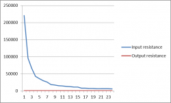
I did some measurements for the input and output resistance. So far I have only measured the first 30 steps or so. The graph looks like the image below. The output resistance is around 300 ohms. If I advance the control a lot it eventually peaks at about 47K, but only for a few settings. The input resistance varies considerably, but on some settings goes as low as 300 ohms. I am no expert but 300 ohms seems far too low to be driven properly.
The resistors are through hole, so they could be replaced. Problem is I am not sure how it has been configured. I will try and trace the wiring.
Any thoughts on the values or how to correct?
The resistors are through hole, so they could be replaced. Problem is I am not sure how it has been configured. I will try and trace the wiring.
Any thoughts on the values or how to correct?
Attachments
Looks indeed not good.
After you figured out the diagram of the device you have, use this to find the correct resistor values:
Logarithmic Attenuator Calculator
After you figured out the diagram of the device you have, use this to find the correct resistor values:
Logarithmic Attenuator Calculator
When measuring, I disconnected the board from the pre-amp, so it wasn't affected by the grid leak resistor. I then put the multimeter either between ground and one channel input for input resistance or ground and output to measure output resistance. I also measured series resistance by measuring from input to output.
- Status
- This old topic is closed. If you want to reopen this topic, contact a moderator using the "Report Post" button.
- Home
- Design & Build
- Parts
- Relay based volume controls on ebay